Return to VK3YE amateur radio projects
|
Dip Oscillator
The dip oscillator is a useful piece
of test equipment for the radio amateur. For further information on its uses, see test equipment.
The circuit below is an example of a dip oscillator. The basic circuit has been described by Drew
Diamond VK3XU in Amateur Radio
magazine. The circuit presented here is
my version of this design.
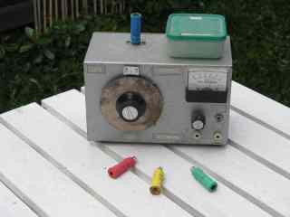
 The unit features four plug-in coils for frequencies between 2.6 and 55 MHz. The coils are mounted on 12mm formers glued to 5-pin DIN plugs. A two gang, air dielectric variable capacitor (salvaged from an old radio) is used as the tuning control. The use of the smaller gang provides better bandspread at higher frequencies. The larger gang is connected when needed (lowest frequency band only). A vernier reduction drive on the variable capacitor makes the instrument easier and more pleasant to use. Wires should be kept short to ensure correct operation at higher frequencies.
In use the variable resistor is set so that the meter needle is near two-thirds scale. Bringing the coil close to a tuned circuit and adjusting the variable capacitor should result in a dip of the meter needle when the dip oscillator's tuned circuit and the tuned circuit under test resonate at the same frequency.
Items were chosen for likely usefulness and a satisfaction rating of 4/5 or better.
|
Books by VK3YE
Ham Radio Get Started (USA)Australian Ham Radio Handbook (Aust) More Hand-carried QRP Antennas 99 things you can do with Amateur Radio Getting back into Amateur Radio Illustrated International Ham Radio Dictionary Make your Passion Pay (ebook writing)
All material on this site |