Return to VK3YE amateur radio projects
|
Phasing SSB experiments
While I've been building filter SSB rigs for years, I've had little to do with the phasing method. Possible reasons include being deterred by adjustment difficulties,
the use of rare parts and the complexity of some designs. While technically elegant, phasing SSB can also be difficult for the non-mathematically inclined to grasp.
Simple phasing SSB was popular around 1960 but interest in it declined for a few decades. Some were quite simple. Main stages included a crystal oscillator or VFO,
RF phase splitter network, two balanced modulators, audio phase splitter network and linear power amplifier chain.
The main area where compromises were made was in
the audio phase splitter network because you need a lot of parts to get an accurate phase difference over the full speech frequency range. Consequently opposite sideband
suppression wasn't as good as more expensive filter rigs then coming in vogue. Some phasing rig designers opted for a narrow transmit audio bandwidth, sometimes by
using a carbon microphone. This narrower bandwidth reduced problems with the opposite sideband being insufficiently rejected.
Today phasing is becoming big again due to its use in software defined radios. However it remains a minority method for stand-alone homebrew SSB transmitters and receivers.
My interest in it was ignited by a simple phasing direct conversion receiver described by Rick Campbell KK7B in a recent QRPp from the QRP ARCI. Further digging revealed a 3.5 MHz
phasing transceiver design by SP5AHT that didn't use many more parts than just the receiver.
Particularly appealing is the extreme simplicity and ingenious design of some of these circuits. Key stages are bidirectional and are used on both receive and transmit.
This is possible due to use of passive components for the balanced modulator, phase shift networks and audio filtering.
I did have qualms about their buildability but experimentation with substitutes overcame them. In particular some of the audio inductors and achieving the required audio band pass.
Success came with common speaker transformers and doing the audio filtering at 8 ohms. This allowed the use of smaller (and off the shelf) inductor values and electrolytic capacitors in the filters.
Below are theory and practical articles on phasing SSB.
VK4FN explains the phasing method of SSB (1949) John Duffy's masters thesis (contains detailed descriptions of SSB generation) Understanding phasing SSB by Rick Lyons
VK2ZF phasing transmitter Part 1 (1952) Part 2 Part 3 ZL2AMJ 'Tucker Tin' phasing SSB transmitter (1961) Discussion, circuit and Canadian version W1HIE phasing SSB transmitter (1961) 1978 discussion of above Heathkit SB-10 SSB adapter (manual and circuit)
Solid state adaption of W1HIE transmitter Simple phasing SSB exciter Source unknown - possibly from W1FB QRP Notebook F5LVG valve 3.5 and 7 MHz SSB phasing transmitter W1TAG low frequency phasing SSB exciter W7CMG simple phasing SSB exciter 9 MHz phasing SSB exciter Source unknown SM0VPO 9 MHz phasing SSB exciter JF1OZL 50 MHz phasing SSB transceiver SP5AHT 3.5 MHz phasing SSB transceiver (Polish - use Google Translate if required) PC board source This was based on some earlier Russian designs. (again paste into Google Translate).
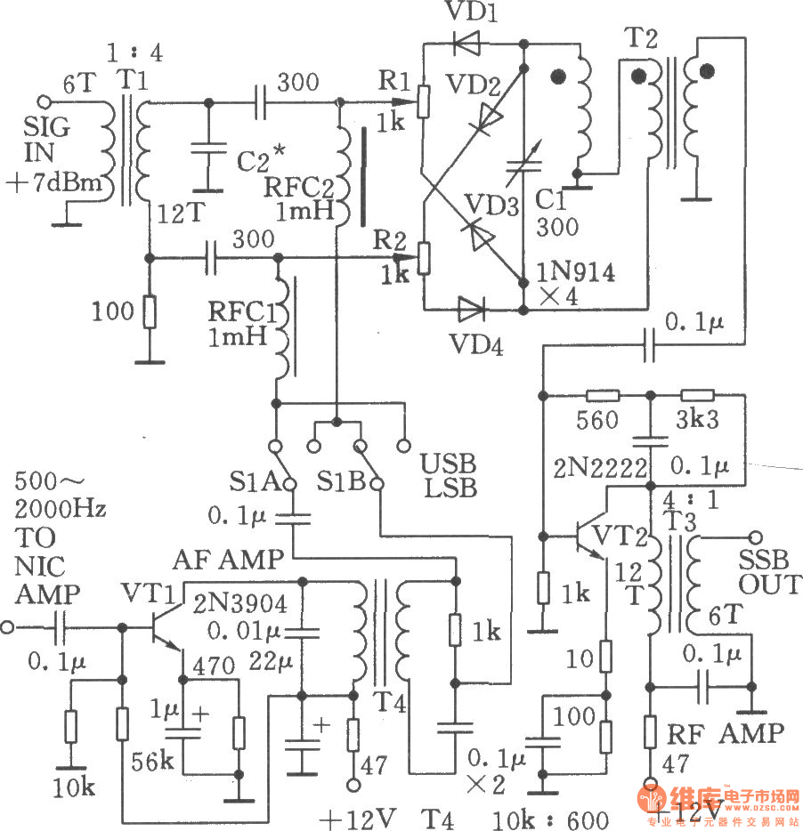
The videos below describe and demonstrate an experimental phasing SSB receiver. It is based on the SP5AHT design with changes described above. There are just 3 transistors (2 in the VFO/buffer and 1 in the RF preamp) plus the LM386 audio amplifier. The audio transformer used after the audio phase shift circuitry isn't critical. I've had success with either a 3k to 3k, 2k to 10k or 1k to 8 ohm. Selectivity isn't brilliant but is better than a direct conversion receiver that has no audio image suppression. You will be able to hear SSB signals 5 kHz apart and mostly separate them. Using two of the 1k to 8 ohm transformers with the 8 ohm sections connected to each other via a 3 kHz low pass audio filter will tighten selectivity.
Can you go even simpler yet still be able to have some rejection of the audio image? Yes it is. Replace the LM386 with a single BC548 transistor audio amplifier and sensitive crystal earpiece. You'll hear many signals if the receiver is built on a band like 40 metres. Some stations several hundred kilometres or more away will even be audible without the RF preamp - ie with just one active device between antenna and earphone. If you're using a 1k to 8 ohm speaker tranformer leave the 8 ohm side unconnected and tap off the audio from the transformer's primary. To get some high frequency roll-off (especially suggested for CW reception) just add a capacitor across the transformer primary. Between 10, 22 or 47nF are good starting points. If there's enough room in the box, something like this would be a great 'drop in' modification for a direct conversion CW transceiver to allow something approaching 'single signal' reception to improve receiver selectivity. If you want more volume try a 2k to 10k interstage tranformer such as this and take the audio from the 10k section. With the RF preamp in I've been able to detect (but not understand) strong SSB signals with the earpiece connected across this 10k winding, though output is nowhere near as usable as having the one transistor as the audio stage and not having an RF preamp. While I haven't tried it, a phasing SSB 'crystal set' is potentially feasible if you have a very large antenna that can pump more microvolts into the receiver and/or improve the efficiency of coupling between the antenna and the product detectors.
It's a myth that you need complex test equipment to set up a phasing receiver. The videos above give some ideas. If the phasing receiver is working there will be a much louder volume on one side than the other as you tune across a carrier signal. As you tune from low to high towards a carrier you will first hear a high pitched tone that will get lower as you tune up in frequency. This is the upper sideband. Then once you pass through zero beat the pitch rises again. This is the lower sideband, which is the desired side assuming you want an SSB receiver for 3.5 or 7 MHz (where lower sideband is used). Your challenge in adjusting the RF phasing potentiometer is to arrive at a 'sweet spot' setting that has one side much louder than the other when you tune across a carrier. That proves you're getting opposite sideband rejection, ie approaching what is referred to as 'single signal reception'. You can do this on received signals, especially if you can find a steady unmodulated carrier. Another approach is to use a locally generated SSB signal, eg from a good quality QRP rig nearby (eg FT817). A crude way of doing this is to generate white noise by blowing into the microphone and listening to the result on the receiver (without retuning). Flipping between LSB and USB should reveal different volumes. If USB is louder and you want LSB to be louder just swap the connections between the diode product detectors and the receiver audio phase shift network. Adjusting the RF phasing potentiometer should greatly change the audio level on the undesired sideband while having minimal effect on the louder and wanted sideband. The correct position is where you get a null (ie minimum volume) heard on the undesired sideband.
Swapping around some of the stages above lets you generate an SSB signal. It should sound clean, with good carrier suppression, though opposite sideband suppression won't be as good as a commercial rig. Still, the unwanted sideband radiated by a 1 watt transmitter with 10dB suppression will be no worse than one from a kilowatt transmitter with 40dB suppression. The LM386 can be used as a microphone amplifier, and if you're ingenious with the switching it can be the same one used in the receiver. Or, if you're the discrete device type of person, a single transistor can do the job. You can even use the crystal earpiece as a microphone if desired. This doesn't have much bass but is probably quite punchy for QRP work. If your crystal earpiece had a tube that can be screwed off, removing that will produce louder and fuller audio than leaving it on.
I have built an 80m phasing transceiver and can verify that SP5AHT's approach works for that as well. However I found that isolation between stages is important to prevent RF feedback. A video describing it to members of Melbourne's Eastern and Mountain Districts Radio Club is below:
Can you go even simpler? An ultra-minimalist phasing SSB transceiver is likely to include the following stages: To make it vastly better, you will need to add:
* 1 x BC548 receiver RF preamp (to give it adequate sensitivity for good earphone reception in a quiet room) I've had success with phasing transceivers along these lines for both 80 and 40 metres, with lower RF output (around 400mW) with the 7 MHz version. Solid contacts have been made with the latter, with an example described below:
Troubleshooting phasing SSB projects can be harder than with DSB rigs, especially with feedback in the driver and power amplifier stages. This feedback can sometimes come via the 7 MHz tuned circuit on the output of the balanced modulator, made worse by the connection of the capacitor from the receiver RF amplifier (even though power is removed from this on transmit). Increasing value of resistors in the emitter stages of RF amplifiers can aid stability, as can reducing the value of the resistor between base and ground for low level RF amplifiers. The CW operator will not need to have the audio stage switched between rx and tx as there is no speech amplifier. However they will need some means of frequency offset, possibly obtained by having two variable capacitors acting as VXO frequency controls. One of these is used for tx while the other is used for rx, allowing fully variable offset. A narrower audio passband is desirable but if you've got enough gain you can do a lot with R-C filters and/or strategically placed series and parallel capacitors in the audio chain. You will note that even the ultra-minimalist version has not skimped on frequency agility. My firm belief is that a transceiver is only any good if it can get random contacts, and the 'search and pounce' approach this requires is only possible if you're frequency agile. I would much rather have 500mW frequency agile than 5w crystal control. But if you were open to being on a fixed frequency, you could use a higher power crystal oscillator and dispense with the buffer stage. Another thing I wouldn't cut back is the audio phase shift network - the type used by the Russians/SP5AHT is much better than the single resistor/single capacitor type and in my view easier to verify that it's working across different audio frequencies. The video below is Paul VK5PAS receiving a 7 MHz 200mW phasing transceiver such as that described above over about 700km.
EFLOSE on YouTube has a multipart series describing the construction of this transceiver. It's in German but you may still find the diagrams and graphics useful. Part 1 is embedded below. See subsequent parts by searching for 'Kurzwellen SSB Funkgerät'.
Experiments with simple direct conversion phasing SSB gear are highly recommended, especially if you've already worked with non-phasing direct conversion direct conversion receivers and DSB transmitters. Hearing signals with just two active stages between antenna and headphones AND getting opposite sideband rejection is extremely rewarding and one of the great pleasures of receiver construction.
Items were chosen for likely usefulness and a satisfaction rating of 4/5 or better.
|
Books by VK3YE
Ham Radio Get Started (USA)Australian Ham Radio Handbook (Aust) More Hand-carried QRP Antennas 99 things you can do with Amateur Radio Getting back into Amateur Radio Illustrated International Ham Radio Dictionary Make your Passion Pay (ebook writing)
All material on this site |