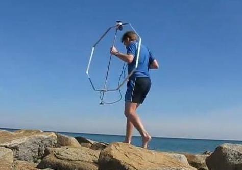
Pedestrian mobile magnetic loop for 40 to 10 metres
I've described a few magnetic loops for HF pedestrian mobile. Some have featured in my YouTube videos and in print (eg see Amateur Radio July 2012, Page 34 for an old version since replaced). This one is my favourite. It's light and robust enough to use for hours at a time yet performs well on the busiest HF bands.
Construction details are below. There's no need to follow them precisely. But if you vary from them, consider the following key trade-offs:
* Size of loop: Bigger is better, but weight and portability suffers
* Shape of loop: Circle is slightly more efficient than square. Octagon is in between.
* Material: Copper better than aluminium due to higher conductivity
* Thickness of material: Thick lowers resistance but adds weight
* Frequency span: Including 50 MHz makes it harder to cover HF bands below 21 MHz in the one antenna. That's important because the lower HF band are more predictable and you want reasonable efficiency there.
* Number of bands: Multiband loops require a wide-range tuning capacitor, whereas it's easier to make your own if covering only a single band
* Connections to capacitor: Directly soldering the main element onto the variable capacitor terminals is electrically better (lower resistance) but mechanically poorer (movement and metal fatigue).
Think about the desired frequency coverage before cutting any metal. For consistent results with QRP over all distances, 7 and 14 MHz stand out as bands to use. Higher bands like 28 MHz are also great fun but are more volatile. While on-paper efficiency on 7 MHz for small loops is low (<10%) its excellent <1000km propagation characteristics and more convivial activity than 20 metres make it a worthwhile inclusion in a magnetic loop.
Main element
I used 25 x 3 mm flat aluminimum strip. These come in 3 metre lengths from hardware stores. I used one full length, bent into an octagon, approximately 90cm across.
Feed arrangement
Feedline braid to bottom centre of loop, directly across from the variable capacitor. A gamma match, making use of stiff 1.5 - 2mm wire, connects to the centre conductor. See video.
Support structure
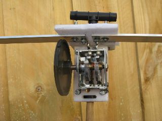
I used 9.5mm timber dowel. Garden irrigation fittings are a snug fit. Cable ties fit this to the loop and capacitor assembly which uses small pieces of kitchen chopping board for support.
Capacitor assembly
With a loop this size 50pF will resonate at just below 14 MHz. If using an air-spaced tuning capacitor it's best to use a two gang unit with the loop connected across the gangs (frame not connected). This places the gangs in series and eliminates frame/rotor resistance which would add loss if only one section was used. Sections in series lower maximum capacitance, so you'll need parallel capacitors to cover the lower HF bands, as discussed below.
My capacitor had 2 x 100pF sections which was ideal. But if you have a larger capacitor you may be able to cover 30 or even 40 metres without parallel capacitors. A large knob fitted aids tuning which is very sensitive.
Two 4mm bolts, protruding about 25mm allow connections of parallel capacitors, used for coverage of lower bands. 4mm is a good size since it mates with readily available banana sockets.
Extra bands
Loop efficiency will suffer but it's definitely worthwhile to add coverage of lower bands, especially 40 metres. Efficiency will be compromised but the band's propagation characteristics and local - medium distance usage more than outweigh this.
Efficiency is vastly reduced again for 80 metres. Nothwithstanding this there are times over short paths where communications with a 1% efficient antenna on 80 metres is better than a 10% efficient antenna on 40 metres due to differing propagation characteristics.
In my loop 40 metres required 150pF parallel capacitance while 80 metres required 750 pF. If you do wish to obtain entire band coverage you will need more variable capacitance than the 50pF in my loop. The parallel capacitor needs to be suitable for RF and have a high voltage rating (630 volts or higher suggested, even with QRP).
160 metres requires about 2800pF. I would not expect this to be much good except for receiving where the loop's performance is excellent.
I did not make a plug in capacitor for 30 metres as this band is predominently CW and digital rather than SSB modes. If your variable capacitor is much bigger than 2 x 100pF then you won't need one. I would suggest a value between approximately 50 and 100pF.
Results
Contacts with this loop has been made on most bands between 80 and 10 metres. A comparison with an earlier loop and demonstrations of its use appear in the videos below.
Disclosure: I receive a small commission from items purchased through links on this site.
Items were chosen for likely usefulness and a satisfaction rating of 4/5 or better.