Magnetic loop antenna for 160 - 15 metres
Another item on this website discussed antennas that amateurs use to operate from confined locations. The smallest antenna described for 80 metres was a magnetic loop.
This article provides details needed to build your own.
Description
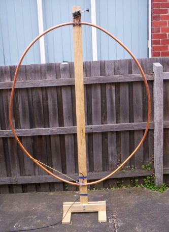
Below is a diagram and some construction details. Note that the element is continuous except for a gap at the top across which the variable capacitor is wired. The feedline is connected to the bottom
of the loop. Dimensions are not particularly critical, provided it is
possible to bring the loop to resonance on all operating frequencies with the variable capacitor used.
Parts
Many of the above items (including the bendable copper tubing) can be bought at
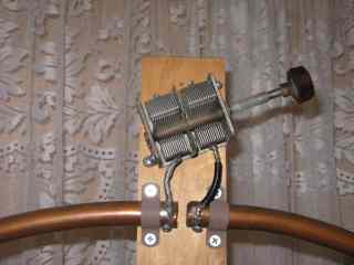
hardware shops. The main exception is the wide-spaced variable capacitor. Try Jackson Bros (advertise in Amateur Radio magazine) or eBay. Other possible sources include old high power transmitting equipment, hamfests
and deceased estates. If your attempts to obtain a suitable
capacitor fail, there is always the possibility of making one.
Disclosure: I receive a small commission from items purchased through links on this site.
Items were chosen for likely usefulness and a satisfaction rating of 4/5 or better.
Construction
It doesn't matter which way you build the loop. I tried it with the feedpoint at the top (as per the diagram) and then inverted it with the feedpoint at the bottom (as per the photo). Both worked well, though I prefer to keep the feedline out of the way, so went for bottom feed.
If the capacitor has two gangs you have some flexibility with how you connect it. Connecting both gangs in parallel increases maximum capacitance, so allows coverage of the low end of the HF spectrum. But it is more lossy and has lower power handling capacity. In contrast, connecting them both in series (done by leaving the capacitor's frame unconnected and connecting the stator plates to each side of the loop) reduces contact losses and arc-over, but may mean that 80 metres is missed. I went for series connection, adding parallel capacitors for 80 and 160 metres.
Adjustment
The object of the adjustment process is to
adjust the position of the 500mm copper tubing along the loop so that the feedpoint impedance equal 50 ohms when the loop is brought to resonance. I should mention that other loop designs sometimes use a smaller inner loop for coupling, but I have found that these are harder to get a good match on all bands.
The first step is to connect the antenna to
an HF receiver tuned to 7 MHz. Set the receiver's RF and AF gain controls to
near maximum and the antenna's capacitor to minimum capacitance (plates fully
unmeshed). Then gradually increase the capacitance. Not much will happen at first,
but the noise from the receiver should gradually start to increase. Further
adjustment of the capacitor will result in the received noise falling. Turn the
capacitor back to the position where the noise peaks. Try this for other bands and frequencies across the HF range - you will find noise can be peaked within an HF frequency range of approximately 3:1 (as mentioned above high voltage capacitors are wired in parallel with the tuning capacitor to cover lower bands like 80 and 160 metres).
A resistive antenna bride is quite useful so adjustments can be made without causing interference. It's also useful to experiment with applying a carrier and seeing how far you can move frequency without SWR increasing by too much - if the loop is working properly the bandwidth should be much narrower than the wire antennas we're used to. If not the loop is likely to be lossy - possibly due to resistance introduced by bad connections or an inefficient tuning capacitor.
When making these adjustments, there is a
temptation to leave the transmitter keyed while making changes to the antenna or adjusting the variable capacitor. This should not be done for two reasons.
The first is that the voltages at the top of the antenna element can be quite high (hundreds or even thousands of volts) even with quite low transmitting powers. The second is that the loop is detuned when people are near it. Thus any adjustment made when you are near the loop will not be optimum when you move away. This effect is particularly pronounced on higher frequencies, and
applies to metal objects as well as humans.
Operation
The Q of this antenna is very high. This
means that it can only operate efficiently over a narrow frequency range. Almost every time you change frequency, you will have to change
the setting of the variable capacitor.
As mentioned before, this is done by peaking
the capacitor for maximum received noise at the desired operating frequency. If
the reflected power is high, make further adjustments until it is acceptable.
Again the use of a resistive-type bridge (rather than a conventional SWR meter)
is preferred because of the ability to tune up without causing interference. If you have one add a vernier reduction drive or some other method to allow finer adjustment as this will make tuning the loop easier.
Note that the loop is directional, with a
sharp null when the element is facing the direction of the incoming signal.
This makes its behaviour different to that of full-sized quad elements, where
the null is off the sides of the loop. This directivity can be useful when
nulling out interference. It is also useful to remember when other stations
report difficulty in hearing you - turning the loop may improve your signal.
Results
This loop has been used extensively on various HF bands, mainly 40 metres. Most contacts have been made with the antenna indoors. Though performance is well down on a dipole, contacts into Western Australia and New Zealand have been made with it. Powers of between 5 and 50 watts have been used.
Contests are always good events to test the effectiveness of new antennas. During July 1997's hour-long 3.5 MHz Australasian CW Sprint, twelve contacts were made with the loop. This was despite the added handicap of having to retune the antenna with every
significant frequency shift.
As would be expected, the loop's disadvantage when compared to full-sized antennas falls with increasing frequency. The loop works well for contacts up to about 1000km on 40 metres, while Europeans have been worked on 20 metres.
Conclusion
The magnetic loop is an ideal HF antenna for units, flats or apartments where only a small courtyard or balcony is available. They will also work well indoors. Apart from their small size, other loop advantages include relatively easy construction and the ability to cover several bands.
The antenna described is a compromise, built from available parts. Improvements to the tuning capacitor and connections to it will improve radiated signals. And some sort of remote tuning mechanism will allow operation without leaving your seat.
|