The L-match is the simplest way to transform the widely varying impedance presented by a wire antenna to the 50 ohms required by the transceiver.
It comprises just two components - an inductor and a capacitor. An L-match is particularly suited for backpack style portable operating as they can be made so small and light.
An L-match plus a thin wire antenna is lighter than a coax fed dipole and allows operation on multiple bands as well.
Description
So what is an L-match? It's just two components - an inductor and a capacitor. Both need to be variable to match a wide range of antennas, although it's OK that only one is continuously variable. Usually the coil is tapped while the tuning capacitor is continously adjustable.
The coil can be wound on a piece of 25mm plastic pipe, or if space is limited, on a iron powder toroid. The capacitor can be a plastic variable type salvaged from an AM radio. Both these parts will stand 5 watts QRP power. However if you want to run more power, then you'll need heavier construction, including the use of an air-spaced tuning capacitor.
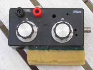
Construction is very simple. No circuit boards are required. However it's a good idea to keep leads short as this will allow the unit to function correctly on high HF bands such as 10 metres.
Usage directions are given above. It's desirable to have some sort of tuning indicator if your rig does not have inbuilt SWR indication. Possibly the most compact is an LED,
though this can be hard to see in bright sunlight.
You may not be able to find the exact parts used but substitutes should be obtainable. Some ideas are listed below.
Variable capacitor
Here you have a choice between a plastic dielectric variable capacitor and an air dielectric type. The plastic type is smaller, lighter and cheaper. However I wouldn't use it with more
than about 5 to 7 watts. The air dielectric version is heavier but can take a higher transmit power and is easier to add a knob to. The value isn't that critical but aim for one with a maximum of around 200pF.
Inductor
Variable inductors aren't as readily available as variable capacitors. Unless you can get a roller inductor you need to make your own tapped inductor as described above. The number of turns
in the circuit can either be varied with a switch or a wander lead with alligator clip. Enamelled copper wire, such as found in old power transformers, is good for the coil windings.
Switch
This coupler calls for a rotary switch. The more positions the more taps you can have on the coil and the wider the range of antennas you can match.
Heavy duty switches are required if you wish to run high power. Another approach, if you don't have a switch, is to use an alligator clip to tap onto various parts of the coil. This works well but
requires the top to be open to permit easy access.
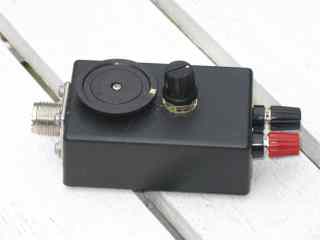
Sockets to connect transceiver and antenna
Common antenna socket types include SO239 (to accept PL259 plugs) or BNC. Some homebrew QRP rigs even use RCA connectors to save money.
Another option is you could have a flylead with plug to fit straight into your transceiver. This may make the coupler harder to pack but means that there's no
risk of you leaving a coax patch lead behind. Another possibility is to use a BNC female as this can plug straight on to BNC equipped transceivers.
Case
Either scrounge a lunch box from the kitchen, make one out of circuit board material or find one in a charity or discount shop.