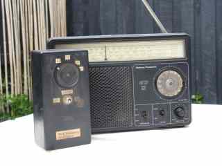
Since most amateurs switched from AM to single sideband more than 40 years ago, it hasn't been possible to receive them with an unaided shortwave receiver. All you'd hear is garbled 'duck talk'. Here's the solution. It's a one-transistor beat frequency oscillator that makes 3.5 and 7 MHz amateur SSB signals intelligble on a cheap receiver.
It is an ideal project for the aspiring amateur, as it allows
them to monitor amateur activity. Its usefulness, low cost, and
ease of construction would make it a good group project for schools,
radio clubs or amateur theory classes.
The device is a miniature transmitter. It provides a steady carrier
signal to the receiver to replace that suppressed within the transmitter
(refer to any radio theory book for a more detailed explanation).
It is the ultimate in simplicity, employing but eight components.
The unit costs approximately ten dollars to build from all-new
parts, and requires no alignment or connections to the receiver.
Anyone with basic soldering skills can construct this project,
and have it working first time.
Though receivers covering the short wave bands are no longer in
every home, suitable sets can be picked up cheaply at garage sales
and swap meets. Tuning the medium wave and one or two short wave
bands, their performance is lacking in many respects. Nevertheless,
they work better than might be expected when used with this circuit.
The reasons for this are given later.
Circuit Description
This unit is a one transistor 3.5 MHz RF oscillator whose frequency
can be varied. As mentioned before, it replaces the carrier in
the receiver that was suppressed during the transmitter's SSB
generation process.
A 3.58 MHz ceramic resonator sets the oscillator frequency. This
two-dollar component is similar to a crystal. Its main advantage
is that it can be shifted over a 100 kHz frequency range by connecting
a variable capacitor in series with it. While the frequency stability
is somewhat inferior to that of a crystal, it is still acceptable
for stable SSB reception.
Because the BFO operates directly on the received frequency, many
of the limitations of low cost AM receivers (such as frequency
drift, coarse frequency readout, hand-capacity and difficulty
of tuning) are either eliminated or made less apparent. This is
because the tuning in of SSB transmissions is effectively performed
by a stable, easy to tune BFO, rather than the unstable free-running
coarse-tuning local oscillator within the receiver. The latter
would have been the case had a conventional 455kHz fixed-frequency
BFO been employed.
The circuit shown (see below) covers the popular 3.525 - 3.625
MHz frequency range. This permits reception of CW and SSB activity,
WIA Divisional Broadcasts and Morse practice transmissions. The
second harmonic of this range covers the 7.050 to 7.250 MHz segment
of forty metres, while the fourth might be useable for twenty
metre reception.
Construction
Virtually any construction method may be used to assemble the
BFO. However, large stray capacitances must be avoided if the
full tuning coverage is to be obtained. Several prototypes were
built. Almost any construction technique can be used.
Full frequency coverage will only be obtained if leads are kept
short. Those to the ceramic resonator and variable capacitor are
particularly critical. Whereas most RF projects are built in metal
cases to provide shielding, the BFO's operation depends on there
being a lack of shielding between it and the receiver. Thus either
a plastic or wooden box is recommended.
Testing/Operation
To verify BFO operation, your AM short wave set is required. Position
the receiver near the BFO, and tune it across the 3.5 - 4 or 7
- 8 MHz frequency range. At a certain point on the dial, the receiver
will go quiet; all normal background noise will be silenced. Switching
off the BFO will restore the normal band noise, while adjusting
the BFO's 'Tune' Control will move the 'silence' to a different
frequency. If the BFO passes these two checks, you know that it
works.
Now switch off the BFO, attach a piece of wire (preferably outdoors)
to the receiver's telescopic antenna, and tune in a strong SSB
signal for maximum volume. Assuming the received signal is within
the BFO's tuning range, it will be possible to resolve the signal
by correctly adjusting the BFO. Place the BFO near the receiver,
and adjust the BFO's tune control until the receiver quietens.
Move the BFO away from the set, and adjust it carefully
until the SSB signal is intelligible. Note that this setting is
critical; the BFO's frequency must be equal to that of the transmitter's
suppressed carrier.
While at first this process is somewhat fiddly,
it becomes easier with practice. For optimum results, experiment
with the physical distance between the BFO and the receiver; weaker
signals require less signal from the BFO (ie a greater separation).
However, it should be possible to find a compromise position for
the BFO where reception from all stations is satisfactory.
Video demonstration of the BFO
Conclusion
A novel device to allow the reception of amateur signals on domestic
AM-only short wave receivers has been described. It is cheap,
very simple to build, and can be expected to work first time.
It fills a definite need amongst potential amateurs, and has the
advantage of being expandable to a direct conversion receiver
or CW/DSB transmitter or transceiver as interest develops.
Note: This article is an abridged and updated version of a full-length
article that appeared in Amateur Radio, October 1997. 3.58 MHz ceramic resonators are available from local suppliers such as Rockby Electronics or online.
Disclosure: I receive a small commission from items purchased through links on this site.
Items were chosen for likely usefulness and a satisfaction rating of 4/5 or better.