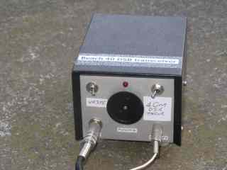
The 'Beach 40' is a simple yet practical voice transceiver for the 7 MHz amateur band. Go any simpler and it's hard to get contacts. And anything more complex often doesn't get finished.
So if you're not quite ready to assemble an SSB transceiver, give this simpler DSB rig a shot.
Key features include:
* Long range 1 - 2 watts output provides contacts up to 1000 km
* Frequency agile covers most of 7 MHz (40 metre) band
* Simple just 6 transistors + 1 IC
* Cheap approx $50 to build from common parts (most from Jaycar)
* Compact good for home or portable
The Beach 40 became a hit as soon as the YouTube video came out. It appeared on
Soldersmoke and got picked up by the Minimalist_QRP_Transceivers yahoo group. Radio club members are also getting involved.
It's a project for the tinkerer. The results are good for the number of parts but refinement is both possible and encouraged. It has a direct conversion receiver and a transmitter controlled by either a wide-swing 'super VXO' or ceramic resonator.
Interested? Watch the videos, draw the circuits and read the notes below. Search 'Beach 40' for others' experiences and improvements. I'll add links to this page as I find them.
Part 1: Beach 40 introduction, circuit description and demonstration
Part 2: Substituting an LM386 audio amplifier
Part 3: Substituting a 'Super VXO'
Part 4: Boosting the LM386 audio amplifier
Part 5: Adding a fine tuning control
Part 6: A smaller case, L-match antenna coupler and RF preamp (Beach 40 Mk II)
Beach 40 construction notes
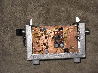
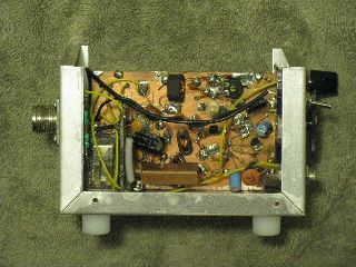
Printed circuit boards discourage experimentation so no layout is provided. Instead assemble it 'dead bug' style on unetched circuit board material, using glued pads to support parts if necessary. Other possibilities include 'grid board' (PC board with copper sawed into pads approx 5mm square with hacksaw and mitre box) or matrix board.
First build the oscillator/buffer using the ceramic resonator. Check it tunes a useful range of 40 metres. The outer leads of the tuning capacitor are bridged to maximise capacitance and frequency range (I get approx 7.050 - 7.200 MHz). Or use parallel crystals as a wide swing VXO. Two cheap 7.122 MHz crystals can tune as low as 7.060 MHz with a carefully selected series inductance (made from several RF chokes in series).
Then make the balanced modulator. Use a 2 hole TV balun former for the output coil and make sure the windings go to the right places. Keep leads short in this and other RF-carrying stages.
The microphone amplifier is next. The circuit is suitable for an electret microphone. If using a dynamic unit leave out the 22k resistor and possibly raise the 100n coupling capacitor value if insufficient or thin audio.
With microphone connected, 12 volts applied and a short lead on the balanced modulator's output, hear yourself on a nearby 7 MHz SSB receiver. Stop talking, tune off to hear carrier note and slowly adjust the balance trimpot near centre position for minimum signal. Do likewise for the trimmer capacitor. Reset the trimpot for the deepest null. This process eliminates the carrier, which is not needed for DSB.
Then build and test the transmit amplifier, driver and power amplifier stages in turn. Output power increases with each added stage. The collector circuit of the first two stages uses a twisted pair of enamelled copper wires threaded through two hole TV balun formers (like that in the balanced modulator). The collector circuit of the final amplifier stage is simpler, using a single thin wire wound through a 6 hole ferrite.
The low pass filter is after the relay, which is controlled by the microphone's PTT. This uses off-the-shelf 1uH RF chokes. Disc ceramic capacitors will work but use better types (eg polystyrene or mica) if you have them for less loss.
The local oscillator and balanced modulator (used as a product detector) is shared with the receiver. All that's needed is an audio amplifier. The high gain LM386 circuit uses gives sufficient gain for headphones and will drive a speaker on strong signals.
Testing involves transmitting, checking output power and voice clarity on a receiver. Tune around the frequency for any undesirable spurii, instability or broadband hash. Layout, shielding and decoupling are all important. Don't build the transceiver so small to make component access and troubleshooting difficult; you will almost certainly have to do it or even change values for best results with your components.
The Mark II version has a receiver RF preamp and inbuilt L-match coupler for end-fed half wave wire antennas. It is also physically smaller and nicer made inside. See Part 6 video above.
It's still under development and more improvements are possible. Eg added receiver audio and RF selectivity, more output power, better frequency stability and more. So build it, use it and tell others how you made yours better.
Component sources
The hardest to find part is the 7.2 MHz ceramic resonator. Try hamshop.cz (English website available).
Also VK5EME at Minikits now carries them. Members could also try the VK QRP Club.
If no luck use a 'super VXO' instead from two parallel crystals as described above. Crystals for 7.122, 7.159 or 7.2 MHz are available off-the-shelf
from some suppliers. Expanded Spectrum Systems sell ham band crystals.
Other parts should be common. If you don't have the binocular style TV balun formers, other ferrite toroids (eg T50-43) should be OK.
On the air
Frequently asked questions
Q. Can the Beach 40 be put onto 80 metres?
A. Most likely, yes. In fact apart from 40 metres, 80 metres is the most suitable band for a homebrew DSB transceiver. You will need to use a different ceramic resonator (3.58, 3.64 or 3.68 MHz are available from VK5EME at the time of writing) and change the values in the pi network.
I suggest values of 820pF, 1.5 nF and 820pF for the capacitors in the pi network and 2.2uH for the inductors in the pi network. If you're adding an external L-match antenna coupler I'd try 10 uH for the inductance and up to 200 or 300pF for the capacitance required.
Q. Can the Beach 40 be put onto 30 metres?
A. Technically it can but many countries prohibit voice modes on 10 MHz. But if you're in a country that permits SSB, I suggest: (a) Replace the 7.2 MHz ceramic resonator with two 10.125 MHz crystals in parallel, (b) add a 4.7 uH inductor in series with the crystals, and (c)
change the capacitors in the pi network to 330, 680 and 330pF. Strictly speaking the 1uH inductors in the pi network should be about 0.8 to 0.9uH but premade RF chokes are less available at those smaller values. An alternative, not tried by me, is to
put 2 x 1.5uH inductors in parallel, or maybe a 2.2uH in parallel with a 1uH to get a lower value (similar to resistors). If your unit is a Beach 40 MkII with an inbuilt L-match coupler reduce the inductor from 6.8uH to 4.7uH.
Q. Can the Beach 40 be put onto 20 metres?
A. It probably can be but you won't get good results. Even 5w SSB can be hard on 14 MHz, and here we're trying something that's much less. You receiver won't be as sensitive and you'll need to hunt around for crystals and experiment with VXO values. If you do go ahead with it,
crystals for 14.200 and 14.318 MHz are available, with the former nearer the more active part of the band. A VXO might cover 20 - 40 kHz. As transistor gain drops off you will require more transmitter stages and transistors with more gain than the humble BD139s which work fine below 10 MHz.
Other videos by VK3YE discuss things to think about when putting homebrew gear onto different bands.
Q. Do you sell the Beach 40 as a built up unit?
A. No. The Beach 40 is a homebrew project that gives the satisfaction of making contacts with a rig you built yourself.
Q. Do you sell the Beach 40 as a kit?
A. No. Clubs or individuals are free to kit the Beach 40 on a non-profit basis. A few DSB kits have been produced over the years. The one most similar to the Beach 40 is VK2DOB's MDT.
Q. Do you sell a Beach 40 printed circuit board or have a pattern for it?
A. No. Printed circuit boards are unnecessary and make future experimentation or modifications harder. Clubs or individuals are free to make circuit boards for the Beach 40 on a non-profit basis.
Q.I am unconfident about building something from scratch without a printed circuit board. What do I do?
A. Building a circuit from scratch is the most important skill in practical electronics. Start with a simple crystal oscillator circuit. Then adapt it to form the oscillator stage in the Beach 40. Video below.
Publication
A two-part article on the Beach 40 appeared in Lo-Key September and December 2013 (Issues 119 & 120), from the VK QRP Club. Please add a 47uF electrolytic capacitor in series with a 22 ohm resistor between Pin 1 of the LM386 and earth on the circuit (page 19). Also the 22 ohm resistor between Pin 5 and the 4.7n capacitor should read 2.2k.
Beach 40 links
Visit the following for others' experiences in constructing this rig:
Disclosure: I receive a small commission from items purchased through links on this site.
Items were chosen for likely usefulness and a satisfaction rating of 4/5 or better.