What can be assembled in a day, doesn't cost
very much, but will give hours of enjoyment? The answer is this
two transistor receiver that anyone can build. It doesn't need an antenna,
gives speaker reception of local AM broadcast stations and also receives
amateurs talking on the 160 metre band.
The performance of this little receiver
surpasses most modern AM broadcast sets - you'll be able to hear interstate
stations that the others miss.
How is this possible with so few parts?
The secret lies in the use of regeneration or positive feedback. By feeding an
amplifier's output back to its input, it is possible to increase the
amplifier's gain. Howeve, the amount of feedback needs to be carefully
controlled; to prevent the amplifier from oscillating.
Regenerative sets were replaced by superhets
in the 1930s because with superhets users did not have to adjust the amount of
feedback (regeneration) when they changed stations. However, in the hands of a
skilled user, regenerative receivers can perform as well as more complicated
superhets. An added benefit of home built sets is that constructors can use
better quality components (such as air-spaced tuning capacitors, vernier dials
and efficient ferrite loopsticks) that are missing on the average pocket
tranny, which is designed for local reception only.
Circuit Description
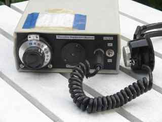
The receiver, dubbed 'The Moorabbin', is a two transistor
regenerative receiver of conventional design. Most parts are mounted on a
printed circuit board that you get to make yourself.
The regenerative detector uses a field
effect transistor (FET). Like with the better valve designs, feedback is
controlled by a variable capacitor. A ferrite rod was used to allow reception
of local stations without an external antenna.
This FET stage forms a complete receiver on
its own, but the audio output is quite low. The received audio is amplified by
an NPN bipolar transistor. The gain of this transistor amplifier is sufficient
to provide speaker reception of local stations in most areas. The 1k to 8 ohm
transformer in the collector allows the set to be used with both low and high
impedance headphones.
Figure One: Circuit diagram
Obtaining parts
The aim of this project was to develop a
simple receiver that could be built with readily obtainable parts. With the
partial exception of the main tuning capacitor, this has been achieved.
Variable capacitor
A 10 to 415 pF variable capacitor was used
as the main tuning capacitor. These are found in valve radios and early
transistor sets. They are rare new but are still common at hamfests. Their wide
tuning range make it possible to cover the AM broadcast band and 160 metres
without having to sacrifice coverage of the bottom end of the broadcast band.
The long shafts of these capacitors also make them easier to use with vernier
dial drives.
Some constructors may wish to build their
set now without waiting for the next hamfest. The first version of the
Moorabbin used a 60/160pF plastic tuning capacitor (same as the regeneration
control) instead of the 10-415 pF unit substituted later. Receiver performance
with the plastic capacitor was good. The main difficulty encountered was
coupling it to the vernier dial. This was overcome by extending the shaft with
a 2.5 mm diameter screw and a spacer. To compensate for the lower maximum
capacitance, more turns need to be wound on to the ferrite rod to cover the
whole broadcast band. Details on this are given later.
Vernier dial
It is possible to get by without a vernier
dial, but using the set will not nearly be as enjoyable, especially if you want
to hear more than just the local stations. Though expensive, it is worth the
cost for the benefits you get. You can sometimes find them at hamfests or online.
Alternatively you could rig up a 'fine tuning' control with a smaller value variable
capacitor or varactor diode-type circuit (which can be done with a regular diode).
Ferrite rod
Ferrite rods in various lengths are available.
If your ferrite rod is too long, saw a notch around it with a hacksaw. The rod
is then quite brittle and can be snapped cleanly in one's hands.
Transistors
Obtaining these should pose no difficulty. A
2N3819 will work equally well as the MPF102 in the detector and a 2N3904 or 2N2222 can be
substituted for the BC548 in the audio amplifier. Note that the lead
connections of substitute transistors may vary from those shown in Figure One.
Audio transformer
1k to 8 ohm audio transformers are less common than they were. One thing you could do if you can't
find one is to replace it with a resistor in the BC548's collector circuit (try 1k to 10k approx) and
wire a high impedance crystal earpiece across it. Or add a coupling capacitor from the junction of the
collector and the 1k-10k resistor (approx 1 to 10 uF) and take the audio off there. It won't be enough
to drive a speaker but you could use an LM386 or similar stage to amplify it.
Enclosure
Enclosures suitable for this receiver are
commercially available or can be made at home. Use a wood or plastic box so
that the ferrite rod is not shielded and local stations can be received without
an external antenna.
The following may assist you in gathering the parts:
Construction
Preparation
Gather all parts and plan how everything
will fit together. Will the tuning capacitor fit inside the case? Does the
ferrite rod need to be shortened? Is the front panel large enough to
accommodate the vernier drive? How will the printed circuit board be mounted?
Will internal leads be short and direct?
Mounting the larger parts
Begin by mounting the larger parts to the
case. Install the vernier drive, both variable capacitors, the switch and
sockets. Figure One shows the front panel layout in the prototype.
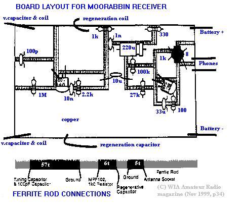
Winding the ferrite rod
The windings on the ferrite rod determine
the receiver's frequency coverage, the ability to obtain feedback so important
to the set's performance and the amount of coupling between the regenerative
detector and any external antenna.
0.4 mm diameter enamelled copper wire was
used for all windings. This diameter is not particularly critical, but 0.4 mm
is easy to work with but still results in fairly compact coils.
Wind all coils the same way around the
ferrite rod. Use pieces of insulating tape to anchor the ends of each coil.
Leave about 2 centimetres distance between each coil. The number of turns for
each coil is shown below. Note that if you're using a plastic
variable capacitor for the main tuning capacitor you will need more turns on
the main coil to cover the lower part of the band. 75 - 80 turns proved
adequate in the prototype.
The ferrite rod should be mounted reasonably
close to both tuning capacitors and the circuit board. Try to keep leads to the
coil 10cm long or less. Find or make some sort of bracket to mount the rod horizontally
in the case. This bracket could use rubber grommets and plastic or be salvaged
from an old transistor radio. If this is difficult to arrange, don't overlook
the possibility of using a ferrite rod longer than the width of the case and
drilling holes in both sides to take the rod.
Etching the circuit board
The next part of building the Moorabbin is
obtaining the printed circuit board. Where does this come from? You etch it
yourself! Don't worry - it's very simple and requires no special tools.
Like with the latest electronic equipment,
components are mounted directly on the copper surface of the board. Surface
mounting makes construction easier and quicker as it obviates the need to drill
holes through the board for each component. It also assists troubleshooting and
modification should this be required later.
Cut the circuit board to size with a
hacksaw. Then clean the circuit board to ensure a quick etch. Sand the copper
surface and finish off with an abrasive powder cleanser (such as Ajax powder)
and scrubbing brush. Rinse and dry with a cloth.
Using Figure Two as a guide, stick pieces
of insulating tape on the areas of copper that will be used to mount components
(light parts get tape).
Figure Two: Circuit board etching
pattern and component placement
Place the board copper side down into a bath
of etching solution of ferric chloride or ammonium persulphate. Use a
non-metallic etching bath and agitate gently to ensure a quick etch.
Mounting the components
Mount the components as per Figure Two.
Check that all polarities and component placements are correct. A good way to
do this is to trace the connections of parts so that they accord with the
circuit and the board layout shown.
Final wiring
Use double-sided tape or stand-offs to
attach the circuit board to the case. Then make all the connections between the
board and off-board parts, such as the ferrite rod, variable capacitors,
sockets, battery snap and power switch. Also check that other off-board
connections are in place, such as between the regeneration coil and the
regeneration capacitor, antenna coil to the antenna socket and the battery snap
to the power switch. Do not overlook the negative (earth) connections joining
both variable capacitors, all sockets, the circuit board and the negative power
lead.
At this point the receiver is complete. Now
time to turn it on!
Switching on
Initial test
Plug in the headphones, connect a wire antenna
(any length) and apply power. Turn the regeneration control fully clockwise (ie
minimum feedback). Unless you are very close to a broadcast station, you will
hear nothing.
Slowly turn the regeneration control
anticlockwise. When you pass a certain point, you should hear a faint hiss in
the headphones. Adjust the main tuning control until you hear an audio tone (or
hetrodyne) which decreases in pitch as you tune towards it. You've just tuned
into your first station! Then carefully back off the regeneration control (turn
it clockwise) until the hetrodyne stops.
Tuning a regenerative set is a two-handed
affair. For peak performance the regeneration control needs to be reset with
every station change. Higher frequency stations will need less regeneration
than lower frequency stations. As you tune lower slowly turn the regeneration
control anti-clockwise to assure best sensitivity and selectivity. Remember
clockwise is minimum regeneration and anticlockwise is maximum regeneration.
Calibrating the dial
To know the frequency to which your receiver
is tuned, you will need to calibrate the dial. This can be done by seeing where
known stations appear on your 0 - 100 dial.
Compare the stations this set receives with
those heard on another AM receiver. Exact frequencies of stations can be found
on the ACMA website. Make a calibration chart showing the station callsign,
frequency and the reading on the vernier dial. Glue this to the top of the
receiver. Do all calibrations with the regenerative receiver set to just after
the point of oscillation for best accuracy.
Refer to the Troubleshooting section if the
receiver misses stations towards either end of the band.
Use without an antenna
The Moorabbin should receive local stations
with just the ferrite loopstick antenna. If stations are weak, turn the
receiver around for best signal. Stations as far away as Newcastle have been
received from Melbourne at night with no external antenna connected. Use
headphones for best long-distance reception.
Volume is better on both local and distant
stations if an external antenna is connected (longer and higher the better). If
overload from local signals is a problem remove turns from the antenna coupling
coil or wire a small disc ceramic capacitor (10 to 100 pF) in the antenna line.
Receiving 160 metres
The Moorabbin is capable of receiving
amateurs using CW, SSB or AM on the 160 metre band. Amateur signals will
usually be weaker than the broadcast stations due to the lower power and
compromise antennas most amateurs use.
Whether you can hear amateurs on your set
depends on several factors. These include the tuning range of your receiver,
noise levels and the amount of 160 metre activity in your area. A vernier dial
also helps - SSB and CW signals can be tuned in with a regenerative receiver
gently oscillating but require greater care in tuning than for AM signals.
Some states transmit WIA broadcasts on 160 metres. SSB stations
can sometimes be heard chatting in the evenings. Morse is mainly used by
operators seeking international (DX) contacts. As well as random contacts,
there is regular scheduled AM activity on 160 metres. Here in Melbourne this
includes the 'coffee break' net after 11am Monday to Saturday and the crossband 'missions'
from 10:30pm Saturdays to the wee small hours of Sunday.
Other stations
Mainstream AM broadcast stations and radio
amateurs are not the only things that can be received on the Moorabbin. There
is a growing number of low power special-interest stations operating between
the end of the official AM broadcast band and 1.8 megahertz. Reception of these
stations is a good test of the Moorabbin's performance. Frequencies such as
1620, 1629 and 1638 kilohertz are particularly popular. Again the ACMA website
lists these stations. When AM stations are very weak it sometimes helps to
listen with the set gently oscillating, rather than back off the regeneration
to just short of oscillation as is often suggested.
Video demonstration of this project
Troubleshooting
If, after applying power, an antenna and
headphones, you can't get the receiver to work, check again that all parts have
been wired correctly. Use your multimeter to check the set's current
consumption. It should be approximately 8mA. Also measure voltages at various
parts of the circuit. If there are significant departures from the values
given, there is likely to be a fault.
The following questions and answers should
cover most of the problems beginners are likely to encounter with simple
regenerative receivers.
Q. What if I hear nothing in the
headphones?
Check all wiring. See that both transistors
are wired in correctly. Also ensure the transformer is connected the right way
- the side with three leads coming out of it is the 1k side which connects
between the BC548 collector and the supply rail.
Touching a screwdriver on the base of the
BC548 is a way to test the audio stage - if you hear nothing the amplifier is
faulty, but if a hum or click is heard the stage is okay.
Q. What if it doesn't oscillate?
Try reversing the connections to the
regeneration coil. If this is not successful, add more turns to the coil and
try both possible connections of the coil. It should be possible to get the
receiver to oscillate with or without an antenna connected.
Q. What if it oscillates over only the
high frequency end?
With this fault good reception of stations
near the top end of the band is possible, but lower frequency stations are weak
and cannot be separated from one another.
Firstly check that your connections to the
regeneration capacitor are right. The tag labelled 'G' should be earthed and
the 'A' tag should go to the regeneration coil. Do not use the 'O' tag - this is
the 60pF section and is too small for our application. If the problem persists,
add a few more turns to the regeneration coil.
Q. The set does not appear to cover
the entire broadcast band.
If the receiver is not tuning high frequency
stations, set any trimmers on the variable capacitor to minimum and try again.
If this makes little difference, remove turns from the tuning coil, a few at a
time, until these stations can be received. When doing this tune to the bottom
end of the band to ensure that lower frequency stations can still be received.
Add turns if you're missing stations near
the bottom end of the band. Again ensure that high frequency stations can still
be tuned in after any changes made.
If a 60/160pF plastic tuning capacitor is
being used for the main tuning control, check that the 'A' tag is being used,
not the 'O' tag. If only a small section of the bottom end is missing, try
connecting the 'O' terminal to the 'A' terminal to increase the capacitor's
maximum capacitance to about 220 pF.
Q. How do I receive 160 metres?
If you're lucky enough to be using a 10-415
pF tuning capacitor, it should be possible to find a number of coil turns that
covers the AM broadcast band to the top end of 160 metres in one range. The set
pictured covers 530 to 1870 kilohertz, which is ideal. If special care is taken
to reduce stray capacitance and inductance, an even wider range is possible.
The first version of this set used 'dead-bug' construction instead of the
circuit board described here. It tuned 480 to 2000 kilohertz - an unusually
wide range for a single variable capacitor and untapped coil.
Those using 60/160 pF plastic variable
capacitors may not be able to achieve a tuning range wide enough for both the
broadcast band and 160 metres. Either compromise by sacrificing the bottom 50 -
100 kilohertz of the broadcast band for 160 metres or add a switch and coil tap
(15 to 20 turns from the end) to provide full coverage over two ranges.
If there is no 160 metre activity while
adjustments are being done, there are several ways to establish the frequency
to which the receiver is tuned. One is to use a dip oscillator, signal
generator or transceiver to produce a local signal on 1.8 megahertz.
Another approach is to use a calibrated SSB
communications receiver. Bring a short pickup wire from the receiver antenna
socket to near the receiver. Bring the set into oscillation with the
regeneration control. It will be possible to find the frequency of the
oscillating set by looking for a carrier on the communications receiver.
Backing off the regeneration should cause the carrier to vanish. This method is
very accurate and is recommended for calibrating the receiver as well as
establishing its precise tuning range.
Q. Why won't the receiver work without
an external antenna?
A. There are two possibilities. Either you
live in a weak signal area, where there are no strong local stations on the AM
band, or you built the set in a metal box. If in a weak signal area, try
listening at night - in all but the most remote localities stations will be
heard with just the ferrite rod.
If you built the receiver in a metal box,
pull the whole thing apart and use a plastic or wooden case instead. Because
plastic or wood allows signals to reach the ferrite rod, you will be able to
use the set without an external antenna in most places.
Q. Don't regenerative receivers cause
interference to other radios?
The early days of radio are full of stories
about the interference that oscillating regenerative receivers caused to other
receivers.
These risks still exist, but are less
significant nowadays. In bygone years people used valve sets with large
antennas. Today broadcast stations are more powerful and no one apart from
long-distance radio listeners connects outside antennas to their receivers.
Also the strength of signals emitted by oscillating transistorised regenerative
receivers is much less than the original regenerative sets, which used valves.
As an experiment, the Moorabbin was brought
to oscillation in the same room as a 10 year old clock radio. The oscillation
was weak in the clock radio at 1 metre distance. At 5 metres it could not be
heard at all. It is thus unlikely that this set will cause interference to
neighbours even when it is used oscillating.
What to do next
This set can be made to operate on lower
frequencies by adding turns to each winding on the ferrite rod and parallelling
all gangs of the tuning capacitor used. Gradually add turns until stations in
the bottom end of the AM broadcast band (530 - 700 kHz) are at the top end of
the receiver's tuning range. The main reason why one would wish to do this is
to receive the aircraft beacons in the 200 to 500 kHz band and to experiment
with receiving the low frequency tests from Tasmania on 177 kHz.
By removing turns higher frequencies can be
covered. This will allow reception of some international shortwave broadcast
stations, VNG/WWV and the eighty and forty metre amateur bands. This is fun to
try, but don't expect top performance; the Moorabbin's plastic case and ferrite
rod are okay on MF but not good for HF.
Good results from regenerative receivers are
certainly possible on HF. A set more suited to HF was described in Amateur Radio June 1998.
This solidly-built receiver uses a metal case, high quality variable capacitors
and vernier reduction drives, voltage regulation, adequate bandspread, and
isolation of the regenerative detector from the antenna to deliver good
performance. Factors such as these make the difference between a mediocre
performer and one that compares favourably with more sophisticated equipment.
Appendix One - Component list for Moorabbin
Receiver
MPF102 FET
BC548 NPN transistor (can be any NPN small signal type eg 2N3904, 2N2222)
180mm ferrite rod (100mm also suitable)
1k - 8 ohm transformer
SPST switch
6:1 vernier reduction drive (optional)
9 volt battery snap
6.35 mm headphone socket
BNC panel mount socket
Sundry items: non-metal case, enamelled
copper wire (for ferrite rod), single-sided PC board material, hook-up wire,
battery mounting bracket, other hardware as required.
Note: This item is an abridged and slightly updated version of a full-length article that appeared in Amateur Radio, November 1999.
Disclosure: I receive a small commission from items purchased through links on this site.
Items were chosen for likely usefulness and a satisfaction rating of 4/5 or better.