The versatile end-fed wire
A piece of wire of almost any length can be
used as an antenna on the HF bands. However, just because an antenna can be
made to work is no guarantee that it will perform efficiently. This article
will initially concentrate on the half wavelength of wire and its use as an
effective multiband antenna. Information on a simple antenna coupling unit and
tuning indicator for use with these antennas is provided towards the end of the
article.
Length
It was mentioned above that the actual
length of wire used in an end-fed antenna is not critical. However, some
lengths are easier to use than others, particularly if multiband capability is required.
Also, very short antennas (significantly less than a quarter wavelength on the
operating frequency) are inefficient, making it hard to put out a good signal.
A length of one quarter wavelength (ie 20
metres on the 80 metre band) is commonly suggested. Though such antennas do
work, an extensive ground system or counterpoise is required for best
performance. Ground systems can require considerable time and effort to install
and detract from the extreme simplicity of these types of antennas.
An alternative is to use a wire of approximately one half
wavelength in length on the lowest operating frequency. An extensive earth
system becomes much less important. Indeed the author has had good results
whilst using no earth at all. However, for certain other reasons (explained
later) some earthing is desirable.
The antenna described here is forty metres
long, or a half-wavelength at 3.5 MHz. As mentioned before, a substantial earth
is not required. Because a half-wavelength piece of wire exhibits a very high
impedence at the operating frequency (and its multiples), some form of coupling
unit between the transceiver and antenna is required. Its function is to
efficiently transform the transceiver's 50 ohm output impedence to the
antenna's high feedoint impedance. Whether a wire antenna has a high or low
impedence is important because it affects the type of coupling unit required as
well as the need for an earthing system.
So what is the impedence of this antenna on
bands other than eighty metres? We already know that a wire that is a multiple
of a half wavelength exhibits a high impedence at the feedpoint. At 21 MHz (15
metres) a forty metre wire is approximately six half-waves long. On 28 MHz (10
metres) it is eight half-wavelengths. Similarly, our wire is several multiples
of a half wave on other HF bands such as 40 and 20 metres. This means that the antenna will always have a feedpoint impedence appreciably higher than 50 ohms and will not require much of a ground system to perform adequately. It is for these reasons that roughly 40 metres is a good length for an end-fed wire antenna for the 3.5 to 28 MHz HF bands.
If you're mainly interested in 7 MHz and up then about 20 metres of wire (ie a half wave on 40 metres) is recommended. The shorter length is lighter to carry when portable, doesn't get as badly tangled and can be more readily supported with a single lightweight 8 to 10 metre fishing pole. It doesn't have to be exactly 20 metres; 18 or 22 metres will perform just as well but may be easier to match as extremely high impedances are avoided.
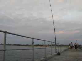
For higher bands like 20 or 15 metres, a length of around 9 - 10 metres will work. The advantage of this is the wire can be run vertically down a 9 metre squid pole. Especially if over water, such as operating from a pier, this should produce a lower angle of radiation, suitable for long distance DX contacts.
Another benefit is there's no need to tie the wire off anywhere so your station takes up less room (good for a crowded location, such as a pier on a summer's afternoon).
Benefits and limitations
Because it is fed at one end, people whose
house is near one boundary of the block will probably find this antenna easier
to put up than a half-wave dipole, which is fed in the centre. Another
advantage of this antenna is that no separate feed line is required. This makes
it particularly attractive for portable use as coaxial cable can be quite
bulky.
What are the disadvantages of this type of
antenna? The first is that it requires a matching unit to operate. Each time
you change band you will need to adjust this for best impedence match between
transmitter and antenna. Another risk with these types of antennas is RF in the
shack. Nevertheless, these two problems are not insurmountable, and the end-fed
wire is one of the most cost-effective multiband antennas available.
Erection of antenna
The antenna should be as high as possible.
Have as much of the wire as possible running horizontal, or nearly so. However,
if this is not possible, don't despair; your antenna will still work. The
antenna is not particularly directional, especially on the lower frequency
bands, so orientation is not that critical.
The type of wire used is also not critical.
Medium gauge stranded insulated wire has given good service in the author's
antennas. Ordinary egg-type insulators can be used to suspend the wire. As an
alternative to purchasing these new, insulators can be made from short lengths
of plastic water pipe or conduit.
Either trees, chimneys or specially-made
masts can be used to support the wire. Two such supports are normally required
for these antennas unless your radio shack is on a second or third storey. In
many cases the second support can be a tree in the backyard. It is not
necessary to climb this to mount the antenna; with a small lead sinker a
fishing line can be thrown over a convenient branch. The sinker is then removed
and the line tied to the antenna's insulator. While observing the sag in the
antenna wire, pull the fishing line tight. Then release it a little and tie it
off at a convenient point. Some sag should be allowed for in wire antennas to
allow for movement of the supporting branch in the wind. Always observe the
usual precautions about keeping the antenna away from power lines and public
thorougfares.
The quickest way of getting an antenna wire up, especially for experimental home or portable use, does not involve climbing or throwing things over trees at all. Instead you simply buy a 8 to 10 metre fishing pole and tie it to a tree or fence post. Lightweight poles will adequately support 20 metres of thin insulated wire end-fed and cost around $50. A recommended supplier is http://www.haverford.com.au who will send anywhere in Australia.
Coupling unit and resistive bridge
The purpose of the coupling unit described
here is to transform the transceiver's output impedence of 50 ohms to the
higher impedence of the wire antenna. Between the matching unit and the
transceiver is a resistive antenna bridge that is switched in to aid the
adjustment of the coupling unit.
An L-match circuit consisting of one
adjustable inductor and one variable capacitor is used here. This is simpler
than most other antenna coupling units which require two or more variable
capacitors, a number of inductors and possibly a switch. This simple approach
is possible as the unit is only required to match a limited range of antenna
impedances.
The resistive bridge is used to show when
the L-match is properly adjusted. Using it is similar to a standard SWR bridge
in that you initially adjust the sensitivity control for full scale on the
meter and adjust the L-match until the reading on the meter is zero (or close
to it). However, the resistive bridge is unlike an SWR meter in that it does
not have a forward/reverse switch. Also, it cannot be left in line while
transmitting. If your rig already has an inbuilt SWR indicator the resistive bridge (diode, resistors, meter etc
part of the circuit) is optional and only the L-match constructed. Further information on operating the resistive bridge is given
later.
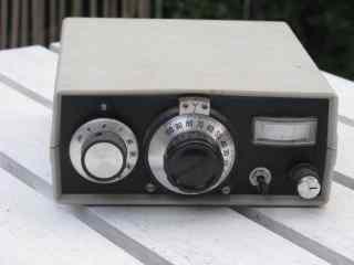
The photo above shows the completed L-match and resistive bridge. The variable capacitor adjustment is in the centre of the front panel. To its left is the ten-position rotary switch for the adjustment of the L-match inductor. The right-hand third of the panel is taken up by the resistive antenna bridge. Below the meter movement is the tune/operate switch and the meter's sensitivity control.
The home-made
tapped inductor is mounted just behind the rotary switch. Alongside the coil,
behind the vernier drive, is the variable capacitor. Most of the remaining
space inside the box is occupied by a piece of matrix board that holds the
parts used in the antenna bridge. Because light weight was important, the
prototype is housed in a commercially-available plastic box. Note that to
accommodate the top of the vernier drive, some plastic has had to be shaved off
inside the top lid of the box. This is slightly visible in the photo.
The variable capacitor used is a rare transmitting-type unit. Unfortunately, these can be hard to come by. Sources include hamfests, vintage radio swapmeets, valve receivers and even one of the older transistorised sets. If you're using low power (up to 5 watts or so) the small plastic dielectric types used in modern AM transistor radios are suitable.
Most variable capacitors that you'll see will have two or three sections or 'gangs'. Simply use only one gang and ignore the rest. The actual value of the variable capacitor is not important provided its maximum capacitance exceeds 150 or 200 picofarads.
A vernier reduction drive and dial adds greatly to the appearance of the finished product and makes adjustment easier. Unfortunately they are rare and expensive new. However if your budget is tight and you are unable to find suitable second-hand reduction drives (they are quite rare), this part can be omitted.
The rotary switch used was a salvaged wafer
switch having ten positions. The switch originally had several sections, so the
unwanted ones were removed and the rear of the shaft cut to size. It is
desirable to have a switch with as many positions as possible to allow more
precise adjustment of the coil. If you are unable to salvage a suitable switch, an alligator clip and wander lead will be just as effective as the switch, though somewhat less convenient to use.
The tapped inductor is the other main
component of the L-match. The coil in the photograph was wound on a piece of
25-30 mm diameter plastic tube. Ordinary thin insulated wire was used in the
prototype. The number of taps needed is always one less than the number of
positions available in your rotary switch - thus the coil here has nine taps.
To make a tap, simply remove about 1 cm of insulation with a knife, form the
bare portion of the wire into a hairpin loop, twist and solder. Hold the iron
on the joint for only the minimum amount of time necessary to prevent the insulation
melting off the wire.
The following table gives the coil taps used
on the prototype. Note that the start of the coil is connected to the antenna
socket and variable capacitor and the wiper of the switch is wired to the
antenna section of the Tune/Operate switch.
Switch position - No. turns from start of coil
1 (fully anti-clockwise) - 55 turns
2 - 30 turns
3 - 20 turns
4 - 13 turns
5 - 9 turns
6 - 6 turns
7 - 4 turns
8 - 3 turns
9 - 2 turns
10 (fully clockwise) - 1 turn
The end of the coil whose taps are closest
together should be nearest the switch. The reason for this is that these taps
are likely to be used on the higher frequency bands, where the effects of stray
inductance are more significant. It is also for this reason that all
connections between the switch and the coil should be short and thick. The coil
is attached to the bottom of the case with a pair of bolts, nuts and 10 mm
stand-offs, which can be made from an old straight-sided ball point pen.
Transceivers with rotary band switches
normally have the lower frequency bands (eg 80 metres) near the
anticlockwise-most end of the switch's rotation and the higher bands (eg 10
metres) selected when the switch is turned clockwise. Similarly, when you turn
the VFO knob of you transceiver clockwise, the frequency selected will
increase.
The controls on the prototype behave in a
similar way. This is achieved by switching in the whole coil (which may be
required on low frequency bands) when the rotary switch is turned to its
anticlockwise-most position (position 1 in the table above) and successively
smaller portions of the coil as the switch is moved clockwise (position 10 on
the table above). These smaller sections of the coil will be required when operating
on higher frequency bands such as 10 and 15 metres.
The variable capacitor is configured in a
simailar way; as the reduction drive is turned clockwise, the capacitance is
reduced, and the unit is tuned to a higher frequency. However, it is important
to note that this cannot be achieved with some variable capacitors because a
clockwise movement in the shaft increases rather than decreases the
capacitance.
Most of the parts for the resistive antenna
bridge are mounted on a piece of unclad matrix board, which is mounted to the
case with screws and stand-offs. Component values are not particularly critical
except for the seven 27 ohm resistors. The function of these resistors is to
provide a reasonably constant 50 ohm load for the transceiver when the L-match
is being adjusted. For this reason they will be required to dissipate a fair
amount of RF power. Two-watt resistors were used in the prototype. This proved
adequate for use with a twenty watt transceiver provided the carrier was wound
down to 5-10 watts and tuning-up was completed in a reasonably short length of
time. Many modern 100-watt transceivers can be wound back to produce the few
watts required for this tune-up process.
No accidents have been had with the
prototype unit. However, if you routinely wish to use it with high power
equipment, and have a habit of forgetting to wind the power back, it should be
possible to replace each 27 ohm resistor with four two-watt 100 ohm resistors
to increase the unit's power handling capacity. Do not be tempted to use
wire-wound resistors - their power ratings may look attractive, but their
self-inductance makes them unsuitable for a project such as this.
The Tune/Operate switch is a medium-sized
DPDT unit. Again, this has given reliable service with 20 watt equipment.
However, it might be wise to use a larger type if you intend to use this unit
with 100 watt gear.
Other parts are not critical. The panel
meter in the prototype was salvaged from a non-working CB transceiver. The scale
was whited out (using correction fluid) and a new one written over it with
biro. This operation calls for a fair degree of manual dexterity - it is easy
to damage the meter movement if you are careless. If in doubt, leave the meter
as is. The variable resistor could also be a salvaged item; in this case the
volume control from a radio or a tape recorder will be fine.
A pair of binding posts was used for the
antenna and earth terminals. Use colour coding to avoid confusion. The
connection to the transceiver is either via a BNC or SO239 socket. Coaxial
cable should be used between this and the transmitter section of the
Tune/Operate switch to minimise stray capacitance and inductance. Either RG58
or RG174 will be satisfactory.
Adjustment and use
Adjusting L-type couplers is simple. Set the
inductance for maximum noise on the receiver. Then adjust the variable
capacitor to obtain a further increase in noise. Apply a few watts carrier and
switch to 'Tune'. Position the sensitivity control so that the meter is reading
full scale. Adjust the variable capacitor for a dip in the reading on the
meter. If it is not possible to get a zero reading, try a different combination
of coil and capacitor settings until this can be achieved. At this point the
system is tuned up, and the unit may be switched to 'operate'. This step
bypasses the resistive bridge and allows the full output from the transceiver
to reach the antenna. Note that when changing bands or making significant
frequency changes within a band, this process should be repeated to assure full
power transfer.
A counterpoise may or may not be required.
Because the antenna is high impedance, adding one will not normally boost
radiation efficiency or materially affect the settings of the L-match. However,
in some cases, going without a counterpoise can cause RF to get back into the
transceiver and spoil operation. A short length of insulated wire connected to
the earth terminal of the L-match minimises this risk. One or two metres is
usually enough.
In practice, the system described has proved easy to use, and represents a good way of getting multi band operation from a
single length of wire. There are no lossy traps or feedlines, and the antenna is easy to erect. Interstate SSB contacts have been made with this antenna on both eighty and forty metres with powers of between two and twenty watts. European and American DX has been worked on the higher HF bands.
While no detailed measurements have been made, performance on the lower bands seems to be roughly similar to a horizontal half-wave dipole at the same height. Theoretically there may be some gain off the far end of the wire on the higher bands, but whether this is useful depends on the wire's orientation and height.
Further ideas and information
Antenna couplers galore More antenna coupler plans and video demonstrations
Parts you'll need
You may not be able to find the exact parts used but substitutes should be obtainable. Some ideas are listed below.
Variable capacitor
Here you have a choice between a plastic dielectric variable capacitor and an air dielectric type. The plastic type is smaller, lighter and cheaper. However I wouldn't use it with more
than about 5 to 7 watts. The air dielectric version is heavier but can take a higher transmit power and is easier to add a knob to. The value isn't that critical but aim for one with a maximum of around 200pF.
Inductor
Variable inductors aren't as readily available as variable capacitors. Unless you can get a roller inductor you need to make your own tapped inductor as described above. The number of turns
in the circuit can either be varied with a switch or a wander lead with alligator clip. Enamelled copper wire, such as found in old power transformers, is good for the coil windings.
Switch
This coupler calls for a rotary switch. The more positions the more taps you can have on the coil and the wider the range of antennas you can match.
Heavy duty switches are required if you wish to run high power. Another approach, if you don't have a switch, is to use an alligator clip to tap onto various parts of the coil. This works well but
requires the top to be open to permit easy access.
Sockets to connect transceiver and antenna
Common antenna socket types include SO239 (to accept PL259 plugs) or BNC. Some homebrew QRP rigs even use RCA connectors to save money.
Another option is you could have a flylead with plug to fit straight into your transceiver. This may make the coupler harder to pack but means that there's no
risk of you leaving a coax patch lead behind. Another possibility is to use a BNC female as this can plug straight on to BNC equipped transceivers.
Case
Either scrounge a lunch box from the kitchen, make one out of circuit board material or consider one of these. But before ordering check it's of sufficient size for the parts used!
Disclosure: I receive a small commission from items purchased through links on this site.
Items were chosen for likely usefulness and a satisfaction rating of 4/5 or better.
An earlier version of this article appeared in Amateur Radio June 1998 with updates made since.
|