Send Morse on your VHF FM rig
Everyone knows that the best way to practice Morse is to use it on the air. But how do you send Morse if you don't have a multimode HF or VHF transceiver? Well, you could hold a
microphone up to a code practice oscillator, and hold the PTT down while pressing the key, but it's very clumsy, and the transmitted tone is likely to be harsh.
Clearly something better is needed.
Enter the MorseBox! It lets you send quality Morse from a normal two metre or 70 centimetre FM transceiver. Just plug it in to the rig's microphone socket and you're on the air.
Using just one transistor and a handful of other parts, the MorseBox can instantly be switched between Morse and speech - a handy feature for those running Morse practice sessions with readbacks.
MorseBox also includes semi-break-in to automatically switch between receive and transmit when the key is pressed and a sidetone to allow monitoring of keying.
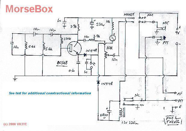
Circuit Description
MorseBox consists of two stages. These are a tone oscillator and a transceiver control/timing circuit.
The tone oscillator provides a pure tone to modulate the transmitter. It is turned on and off by keying the emitter circuit. A twin-T circuit was used because it is reliable and reproducible.
The output is fed to the transceiver microphone connection via a variable resistor which is adjusted to provide a sufficient audio level for the rig used.
The control and timing circuit tells the transmitter when to transmit and when to receive. Pressing the key activates the relay and causes the rig to switch to transmit.
So that the transmitter does not drop out between individual dits and dahs, a large capacitor has been wired across the relay to provide a delay of several seconds. This means that the
carrier is on constantly and makes for more comfortable reception. If the key hasn't been pressed for several seconds, the relay drops out and the transceiver switches to receive.
The delay time depends on the value of the capacitor and the resistance of the relay coil. Slower senders will prefer a longer delay and faster operators will want a shorter delay. The prototype had a
delay of approximately three seconds, which should suffice for Novice speeds. Substituting a smaller value capacitor or lower resistance relay will lessen the delay (and vice-versa).
Experimentation may be required to produce an appropriate delay from the components at hand.
The front-panel switch allows Voice or Morse to be selected. When it is switched to voice, the MorseBox is disabled, and the hand microphone is connected straight to the transceiver.
When Morse is selected the audio from the microphone is cut off and power is applied to the audio oscillator and relay circuits.
A useful feature is the sidetone or keying monitor. This allows you to monitor your own sending without needing a separate receiver. Though an IC audio amplifier and speaker could be used,
this would increase the project's complexity. Instead it was decided to use a small piezo buzzer wired between the supply rail and key as sidetone. The 10k series resistor reduces the
buzzer's volume and extends battery life.
Construction and testing
House the project in a metal case. This is important to prevent the transmitted signal feeding back into the audio oscillator and distorting the tone.
All components except for the capacitor across the key socket, switch, sockets and battery holder are mounted on a piece of unclad perforated circuit board.
The parts were a tight squeeze on the 60x80mm board used in the prototype. 75x76mm boards are commercially available and would have allowed a better layout.
Component leads are passed through the board and are soldered underneath. Vero-type stripboard could be used, but allows a less flexible
layout than the blank matrix board recommended. Because builders will use different component and circuit board types, no component layout diagram is provided.
Instead treat this project as an opportunity to build something straight off a circuit diagram - an important amateur skill.
Before commencing construction, work out where components will be placed on the circuit board. This is particularly important for the larger parts, such as the
relay, electrolytic capacitors and piezo buzzer. Allow space for a hole near each corner of the board to accommodate each spacer. Don't forget to connect the
case to the supply negative line. This can be done in several places - most conveniently through the key socket.
Use a 6.5mm mono headphone socket for the key. The only other socket on the rear panel is the connection to the transceiver. This connection should
have sufficient pins to suit your transceiver's microphone connections. An eight pin microphone socket and detachable patch lead was used in the prototype, but if you're really hard-up,
this can be replaced with a flying lead with plug to suit the transceiver.
Drill two holes in the front panel. One is for the Morse/Voice switch and the other for the microphone connection. No socket was used for the microphone connection
as the ex-commercial microphone used was cheap enough to be sacrificed full-time for this project. However one should be used if you wish to use your transceiver's normal
microphone on the MorseBox. Don't forget the ferrite bead on the connection to the hand microphone - this reduces the risk of transmitted RF getting in to the audio.
Install the wiring around the Speech/Morse switch, relay contacts, the microphone and the socket that carries the connections to the transceiver. Take care as this wiring quite
complicated and it's easy to make a mistake. Trust me, you'll almost certainly get it wrong first time! Use the testing process described later to check for such faults
before the MorseBox is wired to the transceiver.
The power supply used is up to the builder. Batteries were used in the prototype to make the unit fully portable and eliminate the need for an external supply.
A bank of six 'AA' was used in the prototype. This is a good compromise between battery life, size and cost. The small nine volt batteries could be used,
but have limited capacity and may give rise to oscillator chirp near the end of their lifespan.
Schematic diagram
Connecting MorseBox to your transceiver
To connect the MorseBox to your transceiver you will need to make a cable. Because the required connections vary between transceivers, it is not possible to provide
the details here. Instead you will need to study the microphone connections as given in your transceiver's user manual or schematic diagram. Identify the microphone's
basic connections (ground, microphone audio and push-to-talk) and note any other leads that may be present.
Transceiver microphones are full of traps for the unwary. Some PTT buttons do more than just key the transceiver - check for multi-section switches that have other
functions such as disconnecting the microphone element when receiving. Also many microphones have up-down buttons and other functions that require extra wires.
These wires should be provided for in the cable between the transceiver and the MorseBox if these extra features are to be available when the MorseBox is connected.
Be prepared for the possibility that both sides of your rig's PTT connection will be floating above earth. This will affect the way the Morse box is wired to
the transceiver. More specifically, the NO terminal of the relay and the earth side of the microphone's PTT (as connected through the front panel socket) should
be disconnected from earth and wired directly to the (formerly earthed) side of the PTT.
Connecting the MorseBox to the transceiver is the hardest part of the project for the newcomer. This is especially for transceivers with complicated microphone connections.
Seek assistance from a more experienced amateur if in doubt - in extreme cases a wrong connection may damage the transceiver and void the warranty.
Testing and Adjustment
Test the audio oscillator by applying power, switching to Morse and pressing the key. Set the 10k trimmer potentiometer to about half-position. Connect a pair of
high impedance headphones, a crystal earphone or an audio signal tracer to the lead carrying audio to the transceiver socket on the back panel. If all is well you'll hear an audio tone
while the key is down.
If nothing is heard, a wiring fault is likely. Firstly check that the top end of the 3.9k resistor is +9 volts relative to earth. If not, look for wiring errors
near the Speech/Morse switch. Wrong connections in this area could also mean the oscillator is working but audio is not getting to the transceiver socket.
Other reasons for failure include the transistor and the diodes being wrongly connected.
If you've wired in the buzzer, a sound from this should also be heard when the key is pressed. If no sound, check the buzzer's polarity.
Pay attention to the relay's action. Observe it pull in as soon as the key is pressed. The relay should remain in for about three seconds after the key is released. In
Morse mode the relay controls the transceiver's PTT. The three-second delay should be long enough to keep the transmitter keyed down between Morse letters.
Connecting an audible continuity indicator (such as that found in many multimeters) across the earth and PTT terminals on the rear panel socket should result in a
continuous tone while the key is being pressed, only dropping out when three seconds have elapsed after the key was last touched.
Using MorseBox
The Morse Box can be left in the transceiver's microphone lead at all times. The 'speech' setting allows normal voice operation, while the Morse setting allows
Morse to be sent when the key is pressed.
The MorseBox has been set up for semi-break in operation with automatic switching from transmit to receive. Operators can switch to voice at any time with the
Morse/Voice switch. This is useful if doing readbacks after text has been sent.
Most people would be satisfied with using the Morse Box on a two metre repeater or simplex frequency. However, crossband operation (possibly using ten metres,
six metres or 70 centimetres) can assist communication. This is because receiving stations could ask for repeats or request faster sending while the
other station is sending. The effect would be akin to the full-break-in enjoyed by proficient HF CW operators.
Conclusion
A device to allow the transmission of Morse on VHF/UHF FM-only transceivers has been described. It is simple to build and provides an easy way for
amateurs to practice Morse on the air. It would also be an ideal club or group project for those wishing to increase their Morse skills together.
This article appeared in Amateur Radio June 2000 with only minor updates since.
Disclosure: I receive a small commission from items purchased through links on this site.
Items were chosen for likely usefulness and a satisfaction rating of 4/5 or better.
|