Of any electronic project, the crystal set would have to rate as one of the most
popular. Many amateurs are on the air today because of their early
construction of a crystal set. Most practical electronic books for
beginners include at least one crystal set project. Unfortunately, some
of these circuits take simplicity too far and deliver mediocre performance,
often by omitting key components such as the tuning capacitor, or failing to
provide coil taps.
This
article describes a crystal set of medium complexity. It features coil
taps for the antenna and diode to make it useful for both country and
metropolitan listeners. The taps allow the set to cover 160 metres
if desired. All parts are easily obtainable, making it a good choice for
the beginner. The endless possibilities for experimentation also
make crystal sets interesting novelty projects for experienced constructors.
The schematic is shown here:
Obtaining the parts
Tuning capacitor
A
large air-spaced type, covering about 10 to 415 picofarads is
preferred. These capacitors were common in valve and early
transistor radios and often appear at hamfests. Their long shafts make it
easy to attach large tuning knobs. When purchasing one see that the shaft
turns freely, but is not loose. Ensure that the plates are straight and
do not touch when meshed - use a multimeter (preferably with audible continuity
function) to test this. Avoid capacitors with 3/8 inch shafts
unless nothing else is available – knobs for these are not obtainable, and an
old valve radio dial drum will need to be used instead.
If
a large capacitor is unavailable, a small plastic dielectric unit is suitable
(such as stocked by Jaycar and online). The lower maximum capacitance (160 pF) means that
more coil turns are required to provide coverage of the lower end of the
broadcast band. This can be partially overcome by connecting the 60 and
160 pF sections in parallel (link the 'A' and 'O' tabs). The main
disadvantage of these capacitors is their short shafts, which makes it harder
to attach most types of knobs.
Vernier Drive and dial
The
use of a vernier reduction drive is not necessary. However, its inclusion
makes tuning easier, particularly on the higher frequencies. These are rare
new but sometimes come up at hamfests. If your drive lacks a dial, one can be fashioned from
a plastic or metal disc, such as a jar lid or salvaged computer hard disc.
Glue the dial directly to the skirt of the tuning knob if you lack a vernier
drive.
Diode
This
is the most easily obtainable and cheapest component in the
project. A germanium diode, such as a 1N60, 0A90, 0A91, 0A95 or
1N34A will be suitable. The purists still make their own diode
detector with a 'cats whisker' and lump of galena, but modern diodes provide
more stable and repeatable performance.
Headphones
The
very old high impedance headphones are required for this circuit. A
minimum of two kilohms is suggested. Medium impedance headphones (approx
600 ohms) will also work, but are less sensitive.
High
impedance headphones have become difficult to obtain. Alternatives
include:
1. Old-style telephone earpiece. Quite sensitive. Found in the old Telecom corded phones.
2. Crystal earpiece. These are sensitive, easy to obtain
and inexpensive. You may need to connect a 100k - 470k resistor in parallel for it to work properly.
3. Piezo transducer. Believe it or not, these
actually will work as an earphone. Some sizes even fit snugly in the
outer ear in a similar manner to modern earpieces, such as used with mobile
phones. The main drawback with transducers is their peaky audio
response. In some cases it may be
necessary to wire a 100k - 470k ohm resistor across the earphone connections for
correct operation.
4. 1k to 8 ohm audio transformer and standard
low-impedance headphones. Works well, but not as sensitive as a crystal
earpiece.
5. Cheating! Use a transistor or IC amplifier kit
to run a speaker. This approach eliminates the 'free radio' advantage of
the crystal set, but provides louder reception in weak signal areas and allows
speaker listening.
Coil and Coil former
This
needs to be a cylinder about 55 millimetres in diameter and 150 mm long.
The length needs to be long enough to accommodate all ninety coil turns used,
with enough left over for mounting to the front panel. Plastic
pipe, shampoo container or similar will suffice. Though enamelled copper
wire can be used for the winding, the prototype used thin plastic-covered
stranded insulated wire.
Front panel
All
parts are mounted on a 6mm-thick polyethylene chopping board, which forms the
front panel. A hacksaw was used to cut the panel to fit inside the wooden
case. Use the thinnest chopping board available so that the many
screw-mounted sockets used can be fastened properly. The front panel
pictured was cut to 240 mm square.
Case and handle
Use
non-metallic material for the enclosure. The box used in the prototype
was originally a speaker bought cheaply at a school fete. The lid (which
held the speaker) was removed, and the rest of the box painted. The top
carry handle is optional and came from a hardware store.
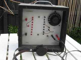
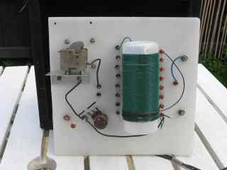
Construction
Commence
construction once all components have been obtained. Plan how the parts
will fit behind the front panel. The diagram and pictures above show
the arrangement used in the prototype. The coil is fastened with stand-offs
and the variable capacitor is screwed to an aluminium L-shaped bracket.
4mm binding posts with banana sockets are used for the antenna and headphone
connections, and 2mm micro sockets for the coil tapping points.
Start
by winding the coil. This consists of ninety turns of thin stranded
insulated wire close wound on a plastic tube approximately 55 millimetres in
diameter. A large number of tapping points are provided so that the user
can vary the set's frequency coverage, and antenna and diode
coupling. This makes it possible to obtain the best compromise
between volume and selectivity for a particular station.
Figure Two shows
the coil construction. Start from the earth end (identified as '0' in the
diagram). Make two holes in the former to anchor the end of the
wire. Wind six turns and then an extra half-turn. With a knife
remove about 1cm of insulation, taking care not to cut the wire.
Form the bare wire into a loop and lightly coat with solder. Do not apply
excessive heat - the wire insulation easily melts. Wind another
five and a half turns and make another tap. Repeat for the
remainder of the coil until approximately ninety turns have been
wound. Add more turns and taps if using a smaller variable
capacitor than specified. Again make two small holes in the former to
anchor the wire.
Place
the completed coil aside and start work on the front panel. Mount the 4mm
banana binding post terminals for the antenna, earth and headphones, as shown
in Figure Two.
Drill holes and mount the 2mm terminals for the coil taps and the antenna,
diode, variable capacitor taps. The tuning capacitor can also be
fastened at this time.
Two
sets of screws and spacers can be used to mount the coil to the rear of the
front panel. A 10mm separation between the coil and the panel is
adequate. Solder in the various components and connecting wires as per
Fig 2. Use insulated wire for the connections between the sockets and to
the variable capacitor. Tinned copper wire can be used for the short links
between the coil taps and the 2mm sockets. Use insulated wire for the
three jumper leads. The jumpers should be sufficiently long to be able to
make connections with all taps along the coil.
This
completes the construction. The panel can now be inserted into the
box. In the unit pictured, the front panel is recessed – this protects
the banana sockets and dial and makes the set more rugged. It also allows
attachment of a hinged lid if required.
Parts List
* 10 – 415 pF variable capacitor x1 (see text)
* 0.001 uF disc ceramic capacitor x1
* 1N60 germanium diode x1
* Vernier dial or drive x1 (optional)
* 2mm micro socket x19
* 2mm micro plug x6
* Banana socket (red) x2
* Banana socket (black) x2
* Insulated wire 20m
* Tinned copper or bell wire 1m
Other items: case and
handle; polyethylene chopping board; Coil former – 55mm dia, 150 mm long;
screws, nuts, washers and spacers; mounting bracket for variable capacitor.
How it works
To receive signals, a radio
circuit must perform three functions: selection, detection and
reproduction.
The inductor and variable
capacitor form a tuned circuit. The role of the tuned circuit is to
select one of the many signals present at the antenna. The size of the inductor
and capacitor determines the frequencies that can be tuned. The capacitor
is made variable to allow the full range of AM broadcast band frequencies (531
to 1602 kHz) to be received.
The diode detector converts
the selected radio frequency signal to an electrical current varying at audio
frequencies.
The headphones convert this
audio frequency energy to sound. The principle is similar to a relay –
the signal cause current to flow in a winding that forms an
electromagnet. The magnetism generated vibrates the metal diaphragm, thus
creating sound. Crystal earpieces perform the same function, but rely on
the piezo-electric effect.
Unlike
in a conventional radio, which uses amplifying devices such as transistors and
integrated circuits, crystal sets are powered by the signal from the incoming
station, so no batteries is required. If provided with an efficient
antenna and earth, crystal sets can receive signals thousands of kilometres
away.
Antenna and earth
A
crystal set requires a wire antenna to operate properly. The longer and
higher it is the better. A length of at least 10 metres in urban areas,
and 20 – 30 metres elsewhere should provide reception in most cases. The
antenna should always be installed away from power lines for safety reasons and
to reduce interference pick-up. An existing amateur or TV antenna
can also be effective, especially if the coaxial feedline is used as part of
the antenna. This is achieved by connecting both the outside and
the inside of the coaxial connector to the receiver's antenna terminal.
An
earth provides stronger signals, and is essential in remote areas. In
homes with copper water pipes, this can simply be a lead to the nearest cold
water tap. In newer homes, where plastic pipes are used, an outside
ground stake can be used instead.
For
long distance reception (hundreds or thousands of kilometres) more than usual
effort needs to be taken when installing the aerial and earth. Reference
One suggests a length of about 100 metres and a height of at least 12
metres. A series of buried radials is suggested for the earth, rather
than the water pipe suggested above.
Operation
Connect
antenna, earth and earphones. Install the three jumper leads. Set
the capacitor tap to near the top of the coil (either the 78th or 90th
turn) and the diode and antenna taps to approximately midway along the
coil.
In
a quiet room, adjust the tuning control and listen for a station. If
several stations are audible, move the diode or antenna taps nearer the earth
end (lower numbered turns) of the coil. This increases the set's
selectivity and makes it possible to separate stations. In a capital city
it should be possible to separate at least nine or ten stations. Optimum
tap settings vary across the broadcast band – lower frequency stations are
often best received with higher tap settings. In rural areas volume is
normally more important than selectivity, so the taps can be moved near the top
of the coil.
Reception
of AM operators on the 1.8 MHz (160 metre) amateur band is possible by moving
the capacitor tap lower down the coil, to the 54th or 66th
turn. Performance will be well down on a superhet or regenerative
receiver, and SSB signals cannot be resolved. Whether you hear amateurs
or not depends on your antenna system and the extent of activity from nearby
operators. Here in Melbourne 160 metre AM activity includes the Monday to
Saturday AM morning net starting at 11am.
In
many areas there are narrowcast stations between the top of the official AM
broadcast band and 160 metres. Because of their low power these stations
will be weaker than the mainstream broadcasters. However these stations
are excellent tests of your receiver and antenna system.
Video demonstrations of this project
Conclusion
A
crystal set of moderate complexity has been described. It is the minimum
required to provide good reception of local stations in urban and rural
areas. However numerous refinements to increase sensitivity, selectivity
or audio output can be made. These include:
1. Double tuned circuits (with variable coupling between
them) to improve selectivity
2. Use of a tuned trap to null out interfering signals
3. Attention to the construction of coils to provide the
highest possible Q
4. Addition of an impedance matching network to provide
efficient power transfer between the antenna and the tuned circuit
5. Use of a large loop antenna for the coil to allow
reception of signals without an external antenna and nulling of unwanted
signals
6. Voltage doubler diode detector circuit using two
diodes to increase volume
7. Use of DC bias (from a DC voltage applied to the diode) or RF bias
(from a locally generated RF signal on the receiving frequency) to improve sensitivity, or,
in the case of the latter, to provide CW and SSB reception.
8. Use of a Q multiplier to increase sensitivity and allow CW and SSB reception.
Should
you decide to experiment with these changes, it would be desirable to keep this
set as a reference and build a second receiver as a test bed for the
experiments.
Obtaining the parts
Suitable parts were discussed in detail above. Many if not all can be bought online.
Variable capacitor and knob
Inductor (insulated wire and cylinder former only required only for this project - other crystal sets use ferrite rods)
Disclosure: I receive a small commission from items purchased through links on this site.
Items were chosen for likely usefulness and a satisfaction rating of 4/5 or better.
Note: This item is an updated version of an article that first appeared in Amateur Radio, December 2000.