Simple test equipment to build
This time we plug in our soldering irons
and put together some pieces of basic test equipment. Though inexpensive, the
projects described will prove useful in the radio shack. Any one of them can be
assembled in an afternoon. They are described in order of complexity, so that
the reader can find a project suitable for their expertise.
Field Strength Meter
A field strength meter is perhaps the
simplest piece of RF test equipment that can be built. Used for checking
transmitters, antenna experimentation, and testing RF oscillators, field
strength meters provide an indication of the presence of RF energy. They are
not frequency sensitive and are useful where indication of a change in level is
more important than the actual strength of the signal indicated.
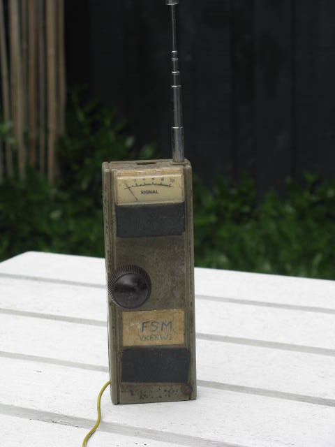
Figure One below shows a schematic of an RF field
strength meter. Like a crystal set, it requires no power source. However,
unlike a crystal set, the meter has no tuned circuit. It responds to signals of
any frequency.
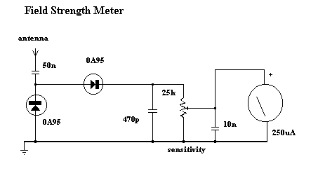
The meter works by converting any RF signal
present at the antenna to a DC voltage. This voltage drives a meter movement to
give an indication of relative RF. The meter includes a control to reduce its
sensitivity where required.
Because it uses few parts, a printed circuit
board is not necessary; components can simply be soldered to one another.
However, a box is desirable for operating convenience. The case and aerial from
a discarded toy walkie-talkie was used in the prototype (see photograph),
though any small plastic case will suffice. The meter movement need not be
large; we are only detecting the presence of RF, and not making precise
measurements.
A meter from an old radio or tape recorder
should work fine. The diodes can be any germanium type; the actual part number
is not important. Germanium diodes can be recognised by their 6mm-long clear
glass case with two coloured bands towards the cathode end. None of the
component values shown are critical; a 50 percent variation would have little
effect on circuit operation.
To test the operation of the meter, a
transmitter is required to provide a source of RF. Placing the field strength
meter's extended antenna near a handheld VHF rig should produce an indication
on the meter, assuming that the sensitivity control has been set to maximum. No
indication means that the meter is not working. Common construction errors
include connecting the diodes or the meter wrongly and using silicon diodes in
place of the germanium diodes specified. In this case, the meter will still
work, but with reduced sensitivity. The earth wire is optional; when working
with low-powered oscillators, it is useful to clip it to ground (of the circuit
under test) to ensure a better indication on the meter.
Those without a transmitter can use an RF
signal generator or crystal oscillator (such as that described later) for
testing purposes. In this case, place the meter's antenna directly on the
output terminal to verify operation. However, only attempt this with
transistorised circuitry; component ratings and safety considerations make the
meter described here unsuitable for poking around valve equipment.
The field strength meter is a useful
instrument in its own right, but it can be made more versatile. Modifications
include adding an amplifier (for greater sensitivity), including a tuned
circuit (so it only detects signals in a particular band), or converting it
into an RF wattmeter and dummy load. Circuits for such instruments are found in
the standard handbooks.
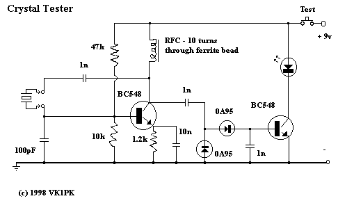
Crystal tester
Below is the circuit of a simple
crystal tester. It switches on a light emitting diode (LED) if the crystal is
working.
The crystal under test is placed in an
oscillator circuit. If it is working, an RF voltage will be present at the
collector. This is rectified (converted to DC) and made to drive a transistor
switch. Applying current to the base causes current to be drawn through the
collector, thus lighting the LED.
If an indication of frequency is required,
simply use a general coverage receiver to locate the crystal oscillator's
output. Note however that when testing overtone crystals (mostly those above 20
MHz) the output will be on the crystal's fundamental frequency, and not the
frequency marked on the crystal's case. Fundamental frequencies are
approximately one-third, one-fifth or one-seventh the overtone frequency,
depending on the cut of the crystal.
The circuit may be built on a small piece of
matrix board and housed in a plastic box. Alternatively, a case made from scrap
printed circuit board material may be used. Either a selection of crystal
sockets or two leads with crocodile clips will make it easier to test many
crystals quickly. The RF choke is ten turns of very thin insulated wire (such
as from receiver IF transformers) passed through a cylindrical ferrite bead.
Its value does not seem to be particularly critical, and a
commercially-available choke could probably be substituted.
The circuit can be tested by connecting a
crystal known to work, and checking for any indcation on the LED. A shortwave
transistor radio tuned near the crystal's fundamental frequency can be used to
verify the oscillator stage's operation. Note however that this circuit may be
unreliable for crystals under 3 MHz, and some experimentation with oscillator
component values may be required.
The crystal checker also tests ceramic
resonators. Other applications include use as a marker generator for homebrew
HF receivers (use a 3.58 MHz crystal) and as a test oscillator for aligning
equipment.
Capacitance meter
This project is more complex than the others
described earlier. However, when finished, you will have an instrument capable
of measuring all but the largest capacitors used in radio circuits. Unlike
variable resistors, most variable capacitors are not marked with their values.
As well, the markings of capacitors from salvaged equipment often rub off. By
being able to measure these unmarked components, this project will prove useful
to the constructor, vintage radio enthusiast or antenna experimenter.
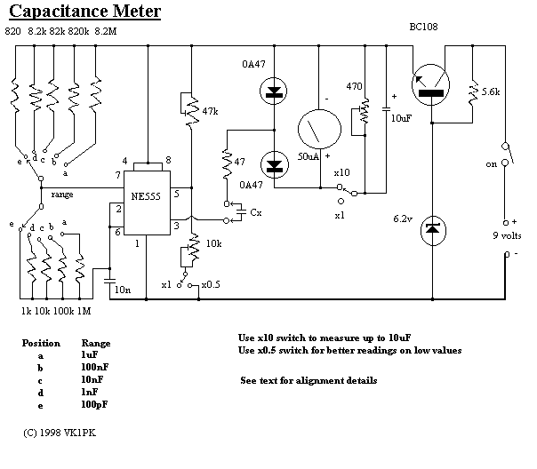
The common 555 timer IC forms the heart of
the circuit (Figure Three). Its function is to charge the unknown capacitor
(Cx) to a fixed voltage. The capacitor is then discharged into the meter
circuit. The meter measures the current being drawn through the 47 ohm
resistor. The 555 repeats the process several times a second, so that the meter
needle remains steady.
The deflection on the meter is directly
proportional to the value of the unknown capacitor. This means that the scale
is linear, like the voltage and current ranges on an analogue multimeter.
The meter has five ranges, from 100pF to
1uF, selected by a five position two pole switch. In addition, there is a x10
switch for measuring higher values and a divide-by-two facility to allow a
better indication on the meter where the capacitor being measured is just above
100, 1000pF, 0.01, 0.1 or 1 uF.
Component values are critical. For best
accuracy, it is desirable that the nine resistors wired to the Range switch
have a 2% tolerance. If 0A47 diodes are not available, try OA91 or OA95
germanium diodes instead. Construct the meter in a plastic box; one that is
about the size of your multimeter but deeper is ideal. The meter movement
should as large as your budget allows; you will be using it to indicate exact
values. A round 70mm-diameter movement salvaged from a piece of electronic
equipment was used in the prototype. The meter you buy will have a scale of 0
to 50 microamps. This scale needs to be converted to read 0 to 100 (ie 20, 40,
60, 80, 100 instead of 10, 20, 30, 40, 50). Use of white correction fluid or
small pieces of paper will help here.
The components can be mounted on a piece of
matrix board or printed circuit board. Use a socket for the IC should
replacement ever be needed. Keep wires short to minimise stray capacitance;
stray capacitance reduces accuracy.
Calibrating the completed meter can be done
in conjunction with a ready-built capacitance meter. Failing this, a selection
of capacitors of known value, as measured on a laboratory meter, could be used.
If neither of these options are available, simply buy several capacitors of the
same value and use the one which is nearest the average as your standard
reference. Use several standards to verify accuracy on all ranges.
To calibrate, disable both the x10 and
divide-by-two functions (ie both switches open). Then connect one of your
reference capacitors and switch to an appropriate range. Vary the setting of
the 47k trimpot until the meter is reading the exact value of the capacitor.
Then switch in the divide-by-two function. This should change the reading on
the meter. Adjust the 10k trimpot so that the needle shows exactly twice the
original reading. For example, if you used a 0.01 uF reference, and the meter
read 10 on the 0.1 uF range, it should now read 20. Now switch out the
divide-by-two function.
If you are not doing so already, change to a
reference with a value equal to one of the ranges (eg 1000pF, 0.01uF, 0.1uF
etc). Switch to the range equal to that value (ie the meter reads full-scale
(100) when that capacitor is being measured. Switching in the x10 function
should cause the meter indication to drop significantly. Adjust the 470 ohm
trimpot so that the meter reads 10. Move down one range (eg from 0.01uF to
1000pF). The meter should read 100 again. If it does not, vary the 470 ohm trimpot
until it does. That completes the calibration of the capacitance meter. Now try
measuring other components to confirm that the measurements are reasonable.
With care, an accuracy of five percent or
better should be possible on most ranges.
Parts availability
Most parts for all three projects should be obtainable. Instances where you might have some difficulty include: (a) Meter movement. These are becoming rarer and dearer. Hamfests and junk equipment
sale are one source. If this fails you could use a digital meter in place of the analogue meter. Or use your multimeter on a low current setting instead. (b) OA47 diodes. Although not exactly the same
germanium diodes as used in crystal sets may be suitable. (c) BC108 transistor. Can be any small signal transistor eg 2N3904 or 2N2222.
Disclosure: I receive a small commission from items purchased through links on this site.
Items were chosen for likely usefulness and a satisfaction rating of 4/5 or better.
Reference
Hawker, P Amateur Radio Techniques, Seventh
Edition, RSGB, 1980
Further reading
A Guide to Test
Equipment
This article appeared in Amateur Radio April 1997 with minor updates since.
|