A longing to build a small transmitter, receiver or piece of test equipment is commonly expressed by many amateurs. All too often, however, the longing remains merely that, due to perceived difficulties in obtaining components, a lack of test equipment, or not having a suitable circuit diagram. Yet, these difficulties can be overcome, and the satisfaction of successfully completing a project is immense. This article aims to answer a few of the questions aspiring homebrewers ask, with some video demonstrations at the end.
Selecting a project
The first step is to determine what you want out of a project that you are considering starting. Is the device being built for the experience and pleasure that its construction provides, or is it to test a particular circuit technique or component? Maybe the project is because commercially made equivalents are unavailable. Alternatively, it could purely be the satisfaction of working the world with a transmitter you built yourself, or of making measurements with test equipment that would be unaffordable if purchased commercially.
Whatever the reason for building, it is important that the features you want are defined, so that a design can be selected to suit your needs. It may happen that you find a description of a project with all the wanted features, and, furthermore, all parts for it are obtainable. A kit for it could even be available. Otherwise, the constructor may prefer to borrow stages from a range of circuits, ending up with a unique device that meets all requirements. This particularly becomes the case for the more experienced experimenter who seldom builds exactly to published designs.
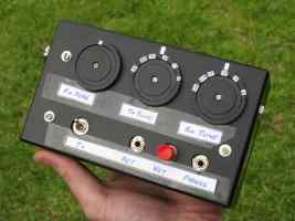
For the beginner though, it is preferable to work from the one design, and not from parts of several. The decision as to which one depends on available components, features provided, the completeness of the project article, along with complexity and cost considerations. For tried, tested but simple HF transceiver designs, I suggest starting with a ZL2BMI rig (for double sideband) or a BitX (for single sideband). A demonstration of a BitX on 40 metres can be watched below.
Sources of information
Homebrewers normally have a wealth of
material on which to base projects. This is obtainable from:-
* Books. There are many
publications available to the amateur experimenter. As well as the
conventional RSGB and ARRL handbooks, more specialised references cover
practical aspects in greater detail. Titles to look out for (whether new
or second-hand) include 'Experimental Methods for RF Design', 'Solid State Design for the Radio Amateur', 'QRP
Notebook', 'Technical Topics Scrapbook', 'G-QRP Club Circuit Handbook', and 'Radio Projects for the Amateur', to name a few.
* Magazines. In addition
to projects in the major amateur periodicals, such as QST, QEX, Practical Wireless, RadCom and Amateur Radio,
there occasionally appear radio projects in general electronics magazines such as 'Silicon Chip'. Some of these designs have the advantage of
a kit being available. However, be wary when considering some ultra-simple projects; for example a crystal-locked 100 milliwatt 80 metre AM
transmitter is simple and cheap, and may well produce a clean signal on an oscilloscope, but is likely to disappoint when used on air under modern band conditions.
As well as being stocked by the larger newsagents, various local and overseas magazines are carried by public, TAFE and university libraries. These normally provide photocopying facilities,
available on a cents per page basis.
In addition, QRP (low power) enthusiasts have their own publications. Probably the best known is 'Sprat',
published by the G-QRP Club, renowned for its technical articles and circuit
ideas. The US-based QRP Amateur Radio Club International issues 'QRP
Quarterly', while the Australian-based VK QRP Club produces
'Lo-Key'. These magazines widely read by those interested in constructing low-powered
transmitters and receivers.
* The Internet, including websites, email lists, discussion forums and YouTube. The greatest ever source of homebrew information, allowing you to tap the collective wisdom of thousands of experimenters around the world. If you have a particular question, want to know how to obtain a part, or simply want to share your
experiences with a particular component or circuit design, there'll be a website, online forum or email list to assist.
Discussion takes place on the homebrew or technical sections on the eHam and QRZ forums. These have a search function and you can find material posted several
years ago. As well there are homebrew amateur radio pages on Facebook. As they say, 'Google is your friend' if you want to find out about anything,
and numerous YouTube videos demonstrate numerous aspects of home construction.
Overall I suggest a mix of information. A few of the major books (eg Experimental Methods for RF Design), subscriptions to some magazines (the QRP ones have particularly low membership fees) and liberal use of the web and email.
Tools and test equipment required
To complete most projects, only basic hand tools will be required. You will also need some items of electronic test equipment. The more useful items are listed below.
If starting out I'd suggest obtaining most items in the Tools list and only some items in the Electronic/radio test equipment list.
* Tools
- Flat and Phillips head screwdrivers - varying sizes
- Long nose and flat pliers
- Wire cutters
- Hobby knife
- Hand drill and drill bits (from 2 to 8mm)
- Tapered reamer
- Hacksaw
- Hammer
- Mitre box
- Set square
- Metal ruler
- Tape measure
- 15 - 40w soldering iron or soldering station with suitably fine tip
- Bright work light
- Magnifying glass (may be on stand)
- 'Helping hands' circuit board holder
- Boxes or tubs for parts storage
* Electronic/radio test equipment and accessories
- Multimeter with transistor tester
- Inductance and capacitance meter (preferably accurate at low values ie uH and pF)
- Audio signal tracer (can be LM386 or similar audio amplifier)
- General coverage HF receiver (included in most HF transceivers)
- Nano VNA or similar network analyser
- Frequency counter up to 1GHz (or you could use an SDR dongle receiver)
- RF power and SWR meter
- RF probe (can fit on to multimeter)
- RF absorption wavemeter or field strength meter (with analogue movement)
- RF milliwattmeter
- RF signal generator (can be made from DDS VFO module or use own transceiver)
- RF attenuator (can be made from resistors and switches)
- Low noise regulated power supply (12 - 14v up to 2 amps approx for most projects)
- Audio spectrum analyser (can be a cheap mobile phone app eg Frequensee for Android)
- Dip oscillator or antenna analyser
- Oscilloscope
(You don't need all that. A handy guide to the most useful test items is here.)
Parts to start with
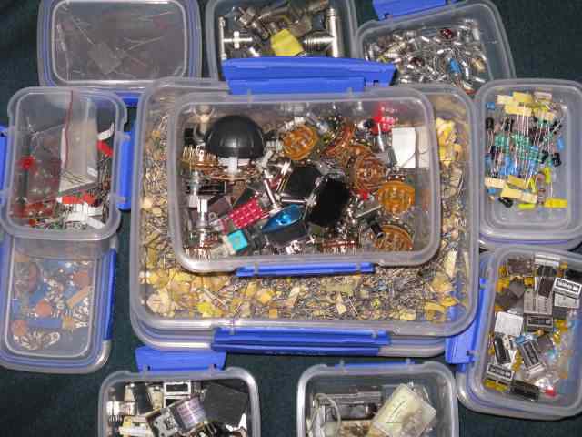
As well as basic tools from the list above it's worth getting some basic components that you'll never have too many of. This lets you build a wide range of projects without having to visit the parts
store or wait for an online order to arrive. Some recommendations on what to get are at Parts needed for electronics
and radio construction.
Circuit construction methods
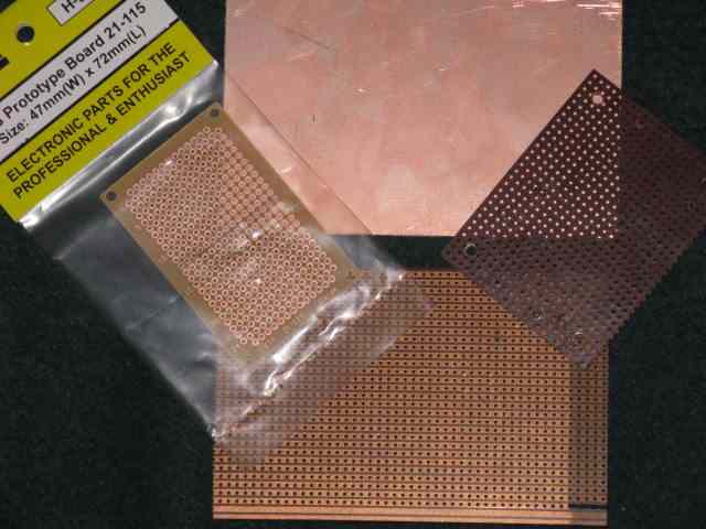
While the through-hole printed curcuit board was almost universally used for manufactured electronic equipment (though it is now being replaced by surface mount technology) and kits, there is no reason for the home constructor to use this form of construction for their projects. While conventional circuit boards look neater than some other techniques, they suffer from the disadvantage of requiring a new board to be etched if substantial modifications to the project are desired. Further time is wasted if these do not perform as envisaged. Thus, unless you know the circuit is reliable, it is worthwhile to consider alternatives to the conventional PC boards, particularly if your project uses only discrete components.
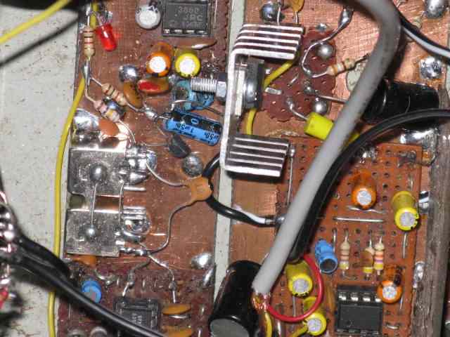
One such alternative is to use an etched printed circuit board, but solder components onto the copper side of the board. This obviates the need to drill holes, and makes it easier to make changes. If no ICs are used, there is no need to use chemical resist pens or photographic methods to produce a board; the use of small pieces of adhesive tape placed on the parts of the board where you want the copper to remain will suffice for smaller projects.
The 'paddyboard' form of construction, popularised by Drew Diamond, VK3XU is also suited to smaller projects for which the ultimate in small size is not required. While, like the above methods, it uses PC board material, paddyboard requires no etching; component leads not connected to the copper surface are soldered to small 5x5 mm square insulated pads, made from spare PC board material. These pads may be glued or soldered to the main board. It is very easy to add extra components and even modify circuit layout. Again, paddyboard is most suited to circuits not containing ICs, though this limitation can be overcome if ICs are mounted on small pieces of vero or matrix boards beforehand. The use of high-value resistors (several megohm) as standoff insulators, soldered to the main board is another approach that has worked well. All of the construction methods mentioned so far are suitable for audio, HF, VHF, and perhaps UHF projects.
If compact construction is required, but the constructor is unwilling to use a conventional PC board, matrix board is a good alternative. Having holes punched every 2.5mm, IC projects can be quickly assemled. Matrix board has worked well for RF projects well into the VHF region, and is stocked by the normal parts suppliers.
A refinement of matrix board is veroboard. This is matrix board with a series of parallel copper strips, which can be cut as required by using a drill bit held in the hand. While suitable for power supply and audio projects, the capacitances between the long parallel strips may impair the performance of RF projects. Veroboard can be made into matrix board simply by immersing it in a bath of PCB etchant solution.
Approach to construction and troubleshooting
Once all components to build a particular project have been gathered, and a construction method has been decided upon, the project can now be assembled. If a simple project, or a well-known design, the entire board can be assembled in the one sitting. Otherwise, if the project is an unfamiliar circuit, or has various stages derived from several sources, it is preferable to build, test, and experiment one stage at a time, before moving on. For this type of construction, where the developmental prototype becomes the final model (possibly after several changes), one can easily see that an adaptable construction method, such as 'Paddyboard' or the use of matrix board is preferable to a PC board, where significant changes require a new board to be etched.
For a large project, such as a large receiver or transceiver, it is desirable that, rather than mounting the entire circuitry on one large board, several smaller boards be used instead. This modular approach to construction permits the project to be an evolving piece of equipment, with additions able to be made as time, inclination and funds permit. This method is also compatible with the 'build and test' approach recommended previously and the desirability of having RF-sensitive stages shielded from one another.
If the project involves RF (especially if it is a transmitter or power amplifier), the box housing it should be shielded. This does not neccesarily mean a conventional metal case is required; boxes made from printed circuit board material is also effective.
The most important aid to trouble-shooting is an ability to think logically. The posession of most of the test equipment mentioned above, plus a schematic diagram of the circuit under test are also desirable. Generally, with trouble-shooting, one checks the overall equipment, by identifying which functions do and do not work, and then attempts to isolate the area of the fault.
In the case of home built equipment under development, it is often not so much a fault, but a performance deficiency that needs to be remedied. This may simply entail the use of a slightly different circuit value for a particular component, or may require the redesign of a whole stage to perform to the specifications required; hence the earlier emphasis on flexible construction methods.
Videos of homebrew radio projects (some with circuits)
Safety
It is not out of place here to discuss electrical safety. The construction of equipment containing high voltages require a change to one's working habits, to minimise the risk of electrocution. The following list, while not exhaustive, shows examples of precautions that should be always taken:-
* Do not work on live equipment (switching off is not sufficient - unplug it from the wall)
* Discharge electrolytic capacitors before working on a project
* Insulate exposed high voltage points in equipment where possible
* The current ratings of fuses should be related to the expected current consumption of the project, and not to the contents of your junkbox
* Check wiring after construction (preferably by someone other than yourself)
* Use proper plugs for power connections
* Work with one hand behind your back if you must operate on live equipment
* Keep half-built projects and chassis locked away from children
* Electrical safety is covered in some of the references mentioned above. In the meantime, it is wise to steer clear from high voltage projects if you have the slightest doubts about your ability to safely construct them.
Disclosure: I receive a small commission from items purchased through links on this site.
Items were chosen for likely usefulness and a satisfaction rating of 4/5 or better.
Conclusion
While the impression may be conveyed that constructing equipment is an activity calling for a high degree of specialised knowledge, and that it is all too hard for
the average amateur, nothing can be further from the truth. By starting with simple one and two transistor projects and commercially available kits, one's knowledge
will steadily increase to a point where more complex projects can be confidently tackled. By this time, you will be able to construct an item merely from a schematic
diagram, and start to develop one's own designs from sections of circuits gleaned from various publications. Additional information is available from the books linked
to above or at Electronics on the Floor: Videos on basic electronics and construction.
An earlier version of this article appeared in Amateur Radio April 1996 with updates made since.